A tape vacuum pasting mechanism

A vacuum and tape technology, applied in the field of auxiliary equipment, can solve the problems of increasing the scrap rate, affecting the product quality, and the tape effect is not very good, and achieving the effect of tight integration and improving the sticking effect.

Inactive Publication Date: 2011-12-07
SUZHOU NEW DISTRICT KEXING WILL ELECTRONICS
View PDF3 Cites 3 Cited by
  • Summary
  • Abstract
  • Description
  • Claims
  • Application Information

AI Technical Summary

Problems solved by technology

[0003] Since the bonding between the film and the tape is done by physical pressure, the bonding effect of the tape is not very good, and sometimes defects such as bubbles and wrinkles appear, which in turn affects the quality of the product and increases the reject rate of the product

Method used


Image

  • A tape vacuum pasting mechanism
  • A tape vacuum pasting mechanism

Examples


specific Embodiment approach

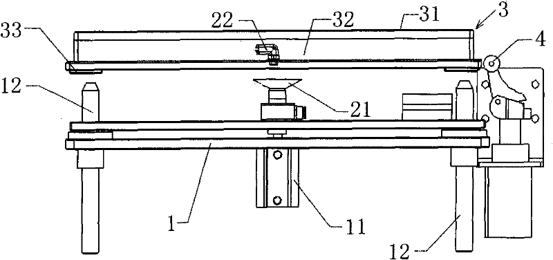
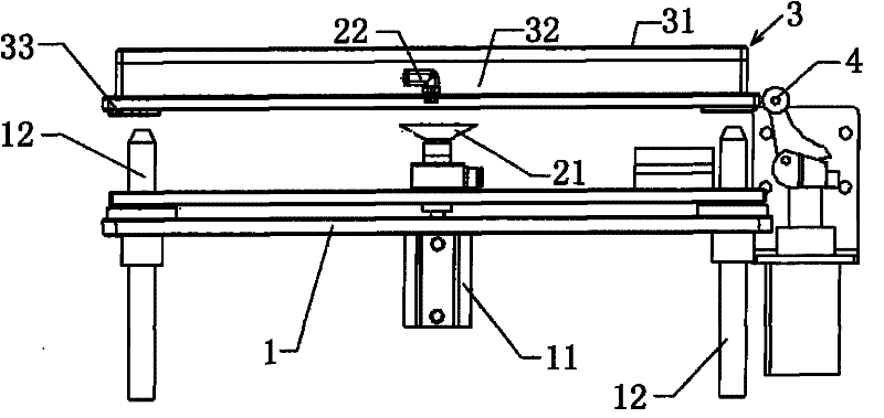
[0017] Such as figure 1 The tape vacuum sticking mechanism shown is a set of mechanisms for sticking tape on the film. The tape is fixed in the form of vacuum adsorption when sticking. Since the tape and film move with the line body / conveyor belt, Therefore, it is necessary to have such a vacuum mechanism at each station to position the film product. The specific implementation is as follows:

[0018] When the transfer tray 3 uses the upper bearing surface 31 to move the film product to each pasting station, the blocking cylinder 4 drives a limit stopper to extend to the side where the tray 3 advances along the conveyor belt to block the tray, and the lifting cylinder 11 rises The positioning pins 12 on both sides of the lifting arm 1 are inserted into the positioning pin holes 33 at the bottom of the tray to lift up the tray 3 together with the film products placed on the carrying surface 31, and at this moment the vacuum nozzle 21 set in the middle of the lifting arm 1 is a...


PUM


Abstract

The invention relates to a tape vacuum sticking mechanism, which comprises a lifting arm driven by a lifting cylinder, positioning pins are arranged at both ends of the lifting arm, a positioning pin hole adapted to the positioning pin is arranged at the lower end of the transfer tray, and a film bearing is arranged on the upper part of the transfer tray. On the surface, there is also a vacuum nozzle on the lifting arm. The lower end of the transfer tray is provided with an air pipe joint suitable for the vacuum nozzle. The air pipe joint is connected to the inner cavity of the transfer tray. through pinholes. The sticking mechanism vacuumizes the inside of the transfer tray with pinholes distributed on the surface by adding a vacuum nozzle and a suction pipe, so that the film placed on the upper part of the tray can be tightly combined with the tape due to the vacuum suction. It is beneficial to improve the paste effect.

Description

technical field [0001] The invention relates to an adhering mechanism, in particular to an auxiliary device used for adhering adhesive tape on a film. Background technique [0002] In the prior art, when completing the operation of pasting the tape on the film, tapes with different directions, positions and sizes must be pasted on the same film; the pasted tape needs to be moved to different stations with the fixture during actual pasting. And when pasting at each station, the position of the corresponding tape needs to remain unchanged, and the jig for placing the tape also runs on the line body / conveyor belt; and when the pallet carries the film product and moves to each pasting station, through The pins driven by the lifting cylinder are inserted into the pin holes at the bottom of the tray to lift the tray together with the film products it carries for further compression, positioning and pasting. After the pasting action is completed, the lifting cylinder comes down ag...

Claims


Application Information

Patent Timeline
Patent Type & Authority Applications(China)
IPC IPC(8): B65H37/04
Inventor 邓波刘瑞勋
Owner SUZHOU NEW DISTRICT KEXING WILL ELECTRONICS
Why Eureka
Try Eureka