Resistance heating evaporation source

A heating evaporation, resistive technology, applied in the direction of vacuum evaporation plating, ion implantation plating, metal material coating process, etc., can solve the problems of uneven material, evaporation material deposition, condensation heating, splashing to the substrate, etc., to achieve Avoid the effect of condensation

Inactive Publication Date: 2011-12-07
SHANGHAI IRAY TECH
View PDF4 Cites 44 Cited by
  • Summary
  • Abstract
  • Description
  • Claims
  • Application Information

AI Technical Summary

Problems solved by technology

[0006] The technical problem to be solved by the present invention is to provide a resistive heating evaporation source to solve the defects caused by the deposition and condensation of evaporated materials at the evaporation port of the crucible and the splashing of materials to the substrate caused by uneven heating inside the crucible.

Method used


Image

  • Resistance heating evaporation source
  • Resistance heating evaporation source
  • Resistance heating evaporation source

Examples


Embodiment 1

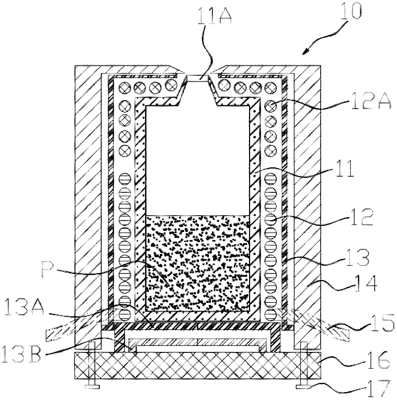
[0035] see image 3 shown. The resistive heating evaporation source includes a crucible 11 containing evaporation material P, an upper heating unit 12A located near the crucible evaporation port 11A, and a lower heating unit 12 located around the main body of the crucible 11 . The crucible 11 is preferably made of transparent quartz, and ceramic materials such as Al2O3, SiO2, PBN are optional; metal materials such as molybdenum and tantalum are optional; two independent heating units 12 and 12A are composed of metal wires or metal sheets, such as molybdenum wire , molybdenum sheets, etc., these two sections of heating units are controlled by two independent temperature measurement units and independent PID temperature control power supply. The evaporation source also includes the outer wall 14 of the evaporation source located outside the entire evaporation source, which is for The entire evaporation source is insulated from heat to prevent the loss of heat inside the evapora...

Embodiment 2

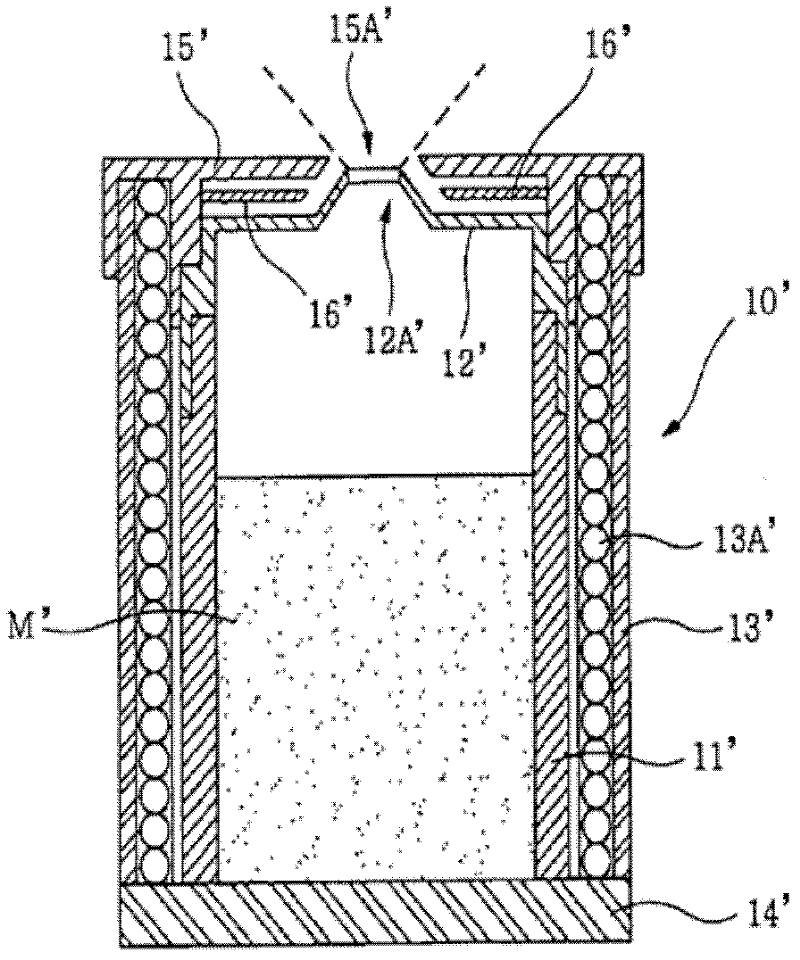
[0040] see Image 6 As shown, the resistive heating evaporation source includes a crucible 21 for containing evaporation materials, and also includes an outer wall 24 of the evaporation source located outside the entire evaporation source, which is to insulate the entire evaporation source and prevent heat loss inside the evaporation source. The source's supporting skeleton. At the same time, a heat shielding layer 23 , a first bottom heat shielding layer 23A and a second bottom heat shielding layer 23B are provided between the heating unit and the outer wall 24 of the evaporation source. Wherein 23A has the function of supporting the crucible 21 . The heating power line 25 is introduced from the side wall, and is generally made of copper wire, and the ceramic insulating sleeve is installed on the surface. The bottom 26 not only supports the crucible but also has good thermal insulation performance, and the material of the bottom is similar to that of the outer wall 24 . Th...

Embodiment 3

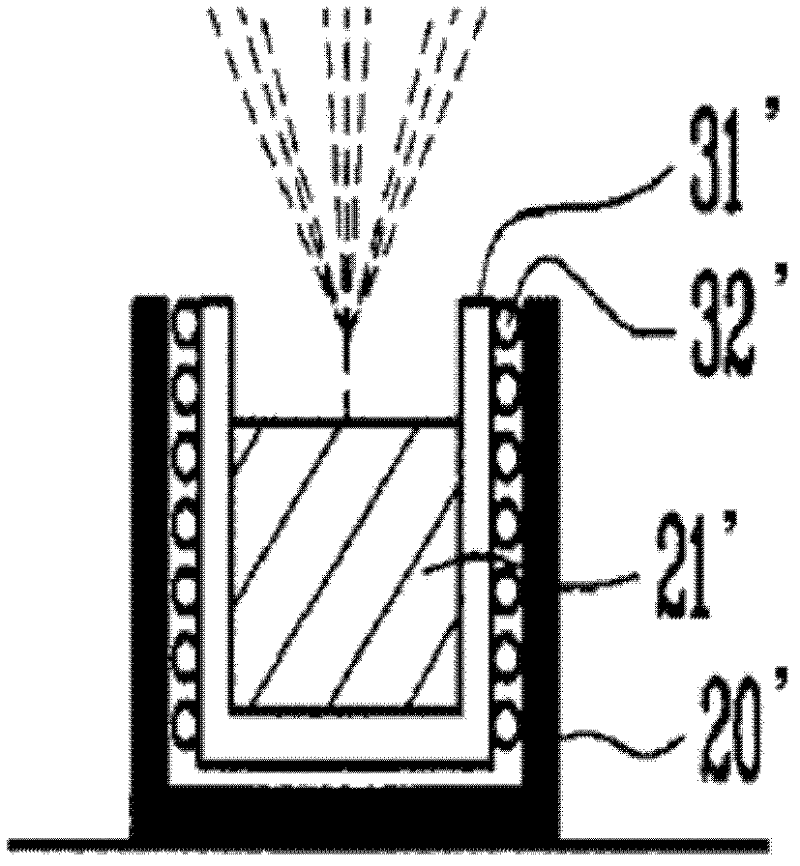
[0043] see Figure 7a As shown, the resistive heating evaporation source includes a crucible 31 for containing evaporation materials, and also includes an outer wall 34 of the evaporation source located outside the entire evaporation source, which is to insulate the entire evaporation source and prevent heat loss inside the evaporation source. It is also an evaporation source. At the same time, a heat shielding layer 33, a first bottom heat shielding layer 33A and a second bottom heat shielding layer 33B are also provided between the heating unit and the outer wall 34 of the evaporation source, generally made of a metal material with high reflection to infrared rays Made, including SUS (stainless steel), Ti, Mn; or add a layer of coating on the metal surface, such as Au, Ag, Al. Wherein 33A has the function of supporting the crucible 31 . The heating power line 35 is introduced from the side wall, and is generally made of copper wire, and the ceramic insulating sleeve is inst...


PUM


Abstract

The present invention provides a resistive heating evaporation source, which comprises a crucible (11) containing evaporation material (P) and provided with a crucible evaporation port (11A), a heating unit surrounding the periphery of the crucible (11), And the source outer wall (14) surrounding the heating unit and the bottom of the evaporation source (16); the heating unit is located on the periphery of the crucible evaporation port (11A), which is used to ensure that the temperature of the crucible evaporation port (11A) is higher than that of the evaporation material ( P) The upper heating unit (12A) with freezing point and independent temperature control, and the lower heating unit (12) located at the periphery of the main part of the crucible (11) with independent temperature control. Since the device is provided with an independent upper heating unit (12A) near the crucible evaporation port (11A), condensation of evaporated materials at the crucible port can be prevented. At the same time, due to the adoption of segmented and independent heating methods, defects caused by material splashing to the substrate caused by local uneven heating are prevented.

Description

technical field [0001] The invention relates to the field of vacuum evaporation coating, in particular to a resistance heating evaporation source. Background technique [0002] In the vacuum evaporation coating industry, the resistive heating evaporation source is one of the most critical components of the evaporation coating equipment, and the internal structure design of the evaporation source is the key to the quality of the film. The invention relates to an internal heating design of an evaporation source and a crucible structure. [0003] figure 1 It is the structure of the traditional evaporation source, see the content published in the patent No. US2007028389. There is no heat preservation cover at the mouth of this evaporation source, and the evaporated material is easy to deposit at the mouth, and the material deposited at the mouth is easily brought by the steam to the evaporation substrate. Moreover, during the heating process, it is likely that the local temper...

Claims


Application Information

Patent Timeline
Patent Type & Authority Applications(China)
IPC IPC(8): C23C14/26
Inventor 程丙勋邱承彬张辉
Owner SHANGHAI IRAY TECH
Why Eureka
Try Eureka