LED drive circuit and control circuit

A technology of light-emitting diodes and control circuits, which can be used in the layout of electric lamp circuits, light sources, electric light sources, etc., and can solve the problems of high cost and heat dissipation

Inactive Publication Date: 2011-12-07
GREEN SOLUTION TECH CO LTD
View PDF5 Cites 21 Cited by
  • Summary
  • Abstract
  • Description
  • Claims
  • Application Information

AI Technical Summary

Problems solved by technology

In the above application fields, the high cost and heat dissipation problems of LED backlights, which were criticized in

Method used


Image

  • LED drive circuit and control circuit
  • LED drive circuit and control circuit
  • LED drive circuit and control circuit

Examples


Embodiment Construction

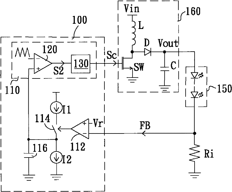
[0042] See figure 1 , figure 1It is a schematic circuit diagram of a LED driving circuit according to a first preferred embodiment of the present invention. The LED driving circuit includes a control circuit 100 and a power conversion circuit 160 for driving an LED module 150 . The LED module 150 has a plurality of LEDs connected in series. The power conversion circuit 160 is connected to an input power Vin to convert (for example: step up or step down) the power of the input power Vin according to a control signal Sc to output an output voltage Vout to drive the LED module 150 to emit light. In this implementation, the power conversion circuit 160 is a DC-to-DC boost conversion circuit, including an inductor L, a transistor switch SW, a rectifier diode D and an output capacitor C. One end of the inductor L is connected to the input power Vin, the other end is connected to one end of the transistor switch SW, and the other end of the transistor switch SW is grounded. One e...


PUM


Abstract

The invention provides a driving circuit and a control circuit for light emitting diodes, and the driving circuit and the control circuit are applied to controlling a power switching circuit to stabilize the output of the power switching circuit. The control circuit comprises a capacitor, a charging unit, a discharging unit, a feedback control unit and a working period adjusting unit, wherein the charging unit is provided with a current source connected with capacitor and is used for charging the capacitor, the discharging unit is connected with the capacitor and used for discharging the capacitor, the feedback control unit controls the charging unit to charge the capacitor according to a feedback signal indicative of an output state, and the working period adjusting unit generates a control signal and adjust a working period of the control signal according to a voltage of the capacitor.

Description

technical field [0001] The invention relates to a light emitting diode drive circuit and a control circuit. Background technique [0002] At present, electricity accounts for 14% of the world's annual energy, while lighting accounts for as much as 22% of the electricity usage. Therefore, under the current trend of global energy saving and carbon reduction, the impact of lighting plays a decisive role. [0003] Today's common lighting sources are mainly incandescent lamps and fluorescent lamps. Although incandescent lamps are low in cost, they do not conform to the current trend of global low-carbon life due to the disadvantages of high energy consumption, low luminous efficiency, and high heat generation. Fluorescent tubes are made of glass and have sockets at both ends to connect to the power supply and fix the position of the fluorescent tubes. Unlike incandescent lamps, fluorescent tubes must be equipped with ballasts (also known as "ballasts"), which cooperate with st...

Claims


Application Information

Patent Timeline
IPC IPC(8): H05B37/02H02M3/07
Inventor 徐献松余仲哲李立民
Owner GREEN SOLUTION TECH CO LTD
Why Eureka
Try Eureka