Optical information analyzing device and optical information analyzing method

An analysis device and analysis method technology, applied in the field of optical information analysis devices, can solve the problems of non-crossing optical axes, scattered light or fluorescence sensitivity error, optical information deviation, etc., to achieve the effect of improving sensitivity and increasing the opening angle of light receiving

Active Publication Date: 2011-12-07
雅马拓科学株式会社
View PDF7 Cites 21 Cited by
  • Summary
  • Abstract
  • Description
  • Claims
  • Application Information

AI Technical Summary

Problems solved by technology

[0005] However, in the conventional device as described above, when the sample flow passes through a position deviated from the center of the flow channel in the flow cell, since the optical axis of the irradiating part is aligned with the sample flow, the light-receiving part may be distorted. The problem that the optical axis of the optical system does not cross the optical axis of the sample flow and the irradiation part
For this reason, the light receiving unit is configured to receive light in a wide range. As a result, the sensitivity of detected scattered light or fluorescence decreases, or the obtained optical information of the specimen varies.
[0006] In addition, in the conventional apparatus as described above, since only one light receiving unit for receiving side scattered light and / or fluorescent light is provided, there may be problems caused by the orientation of the specimen when the specimen is not spherical. Sensitivity errors of scattered light or fluorescence, or sensitivity errors of scattered light or fluorescence caused by the displacement of the sample from the center position in the sample flow when the sample does not pass through the center position in the sample flow, etc. The problem of biased optical information of the specimen

Method used


Image

  • Optical information analyzing device and optical information analyzing method
  • Optical information analyzing device and optical information analyzing method
  • Optical information analyzing device and optical information analyzing method

Examples


Embodiment Construction

[0045] Hereinafter, embodiments of the present invention will be described in detail based on the drawings.

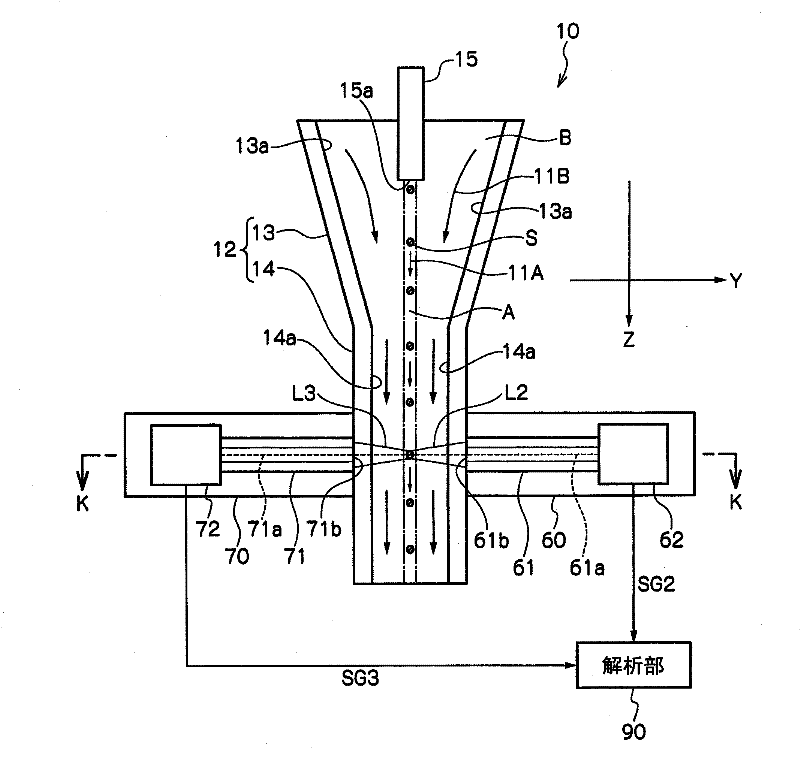
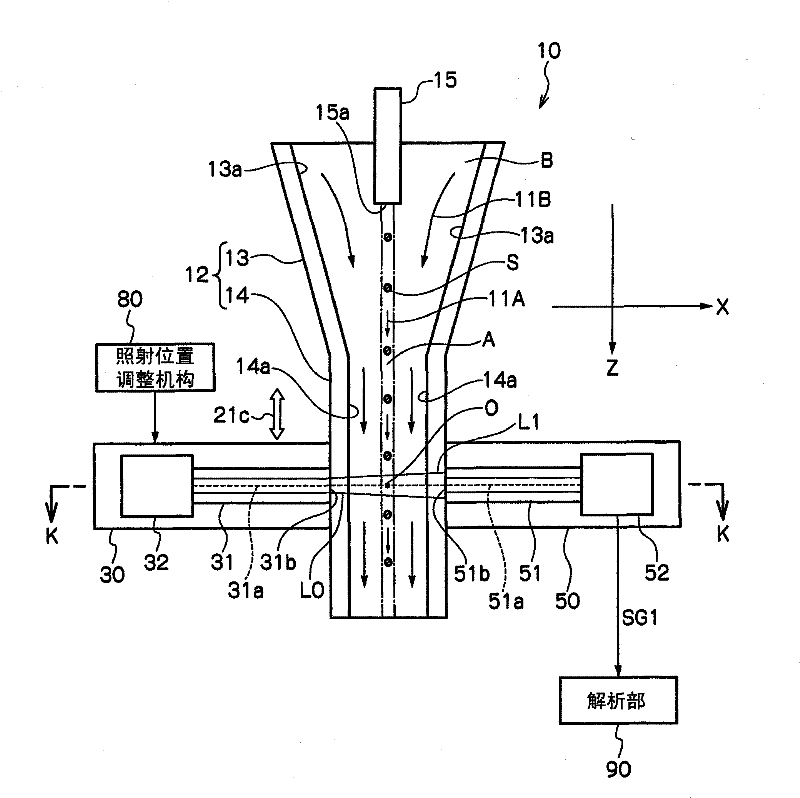
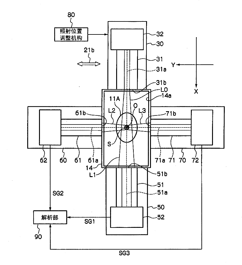
[0046] figure 1 It is a schematic longitudinal sectional view of an optical information analysis device according to an embodiment of the present invention. in addition, figure 2 will be figure 1 The schematic longitudinal section view of the optical information analysis device rotated 90 degrees around the Z axis, image 3 is along figure 1 and figure 2 A schematic transverse cross-sectional view of the K-K line of the optical information analysis device.

[0047] Such as Figure 1 ~ Figure 3 As shown, the optical information analysis device 10 according to one embodiment of the present invention includes: a flow cell 12 having a flow path 13a and a flow path 14a through which the liquid A flows; The liquid A is introduced into the flow path 13a of the flow cell 12; The sample S to be detected; the transmitted light receiving part receives the transmitted li...


PUM

PropertyMeasurementUnit
angleaaaaaaaaaa

Abstract

An optical information analyzer (10) includes a light emitting unit (30) that emits light (excitation light) (L0) to a sample (S), a transmission light receiving unit (50) that receives transmission light (L1), which is the excitation light passing through the sample (S), and detects the received transmission light as a transmission light signal (SG1), scattered light / fluorescence receiving units (60) and (70) that are provided at a plurality of positions, receive side scattered light / fluorescence components (L2) and (L3) from the sample (S), and detect the received side scattered light / fluorescence components as scattered light / fluorescence signals (SG2) and (SG3), and an analyzing unit (90) that measures the optical information of the sample (S) on the basis of the detected scattered light / fluorescence signals (SG2) and (SG3) and the detected transmission light signal (SG1) and analyzes the sample (S) on the basis of the measured optical information.

Description

technical field [0001] The present invention relates to an optical information analysis device and an optical information analysis method. In particular, it relates to an optical information analysis device and an optical information analysis method for measuring optical information of a sample by irradiating irradiation light onto a sample as a measurement target dispersed in a liquid flowing in a channel. Background technique [0002] A device has been proposed (for example, refer to Patent Document 1) in which a liquid containing dyed biological particles (microscopic objects to be examined: specimen) flows through a flow path of a flow path forming member (flow cell) The biological particle is irradiated with the light emitted by the illuminating part (irradiating part), and the scattered light or fluorescent light from the biological particle is detected by the detecting part (light receiving part), thereby obtaining the biological information of the biological particle...

Claims


Application Information

Patent Timeline
Patent Type & Authority Applications(China)
IPC IPC(8): G01N21/53G01N21/64
CPCG01N21/64G01N15/1434G01N2015/1452G01N21/53
Inventor 月井健木村健一高桥亨徐杰
Owner 雅马拓科学株式会社
Why Eureka
Try Eureka