Silo wall rapping air hammer

A technology of air hammer and silo wall, which is used in the field of devices for clearing hopper blockages and making material conveying unobstructed, can solve the problems of safety, large ash content, clogging in silo or cone hopper and other problems, so as to achieve high vibrating force. , the effect of strong dredging ability and low manufacturing cost

Active Publication Date: 2011-12-14
ANHUI KANGDI ELECTRIC POWER SCI & TECH
View PDF2 Cites 19 Cited by
  • Summary
  • Abstract
  • Description
  • Claims
  • Application Information

AI Technical Summary

Problems solved by technology

[0002] During the process of conveying powdery, granular, massive or mixed solid materials, due to the high humidity, high ash content and high viscosity of the material, the material will adhere to the silo wall or be blocked in the silo or cone. Bucket and other containers, or arching in the hopper, resulting in cut-off, affecting the normal and continuous production, especially in the process of transporting raw coal in thermal power plants.
Due to the ash and moisture, the pressure of the upper coal can easily squeeze the raw coal into lumps, causing the coal hopper to stick to coal, canopy coal, arch, and block coal, causing safety hazards and affecting the power generation of the unit
[0003]At present, the more commonly used method is to manually use a sledgehammer to beat the bucket wall vigorously, which is more effective for short-term awning coal, but for longer awning coal If it cannot meet the requirements of the site, it will either set up scaffolding, which will cause personal safety hazards, or stop the machine and enter the inside of the coal hopper for thorough cleaning

Method used


Image

  • Silo wall rapping air hammer
  • Silo wall rapping air hammer
  • Silo wall rapping air hammer

Examples


Embodiment Construction

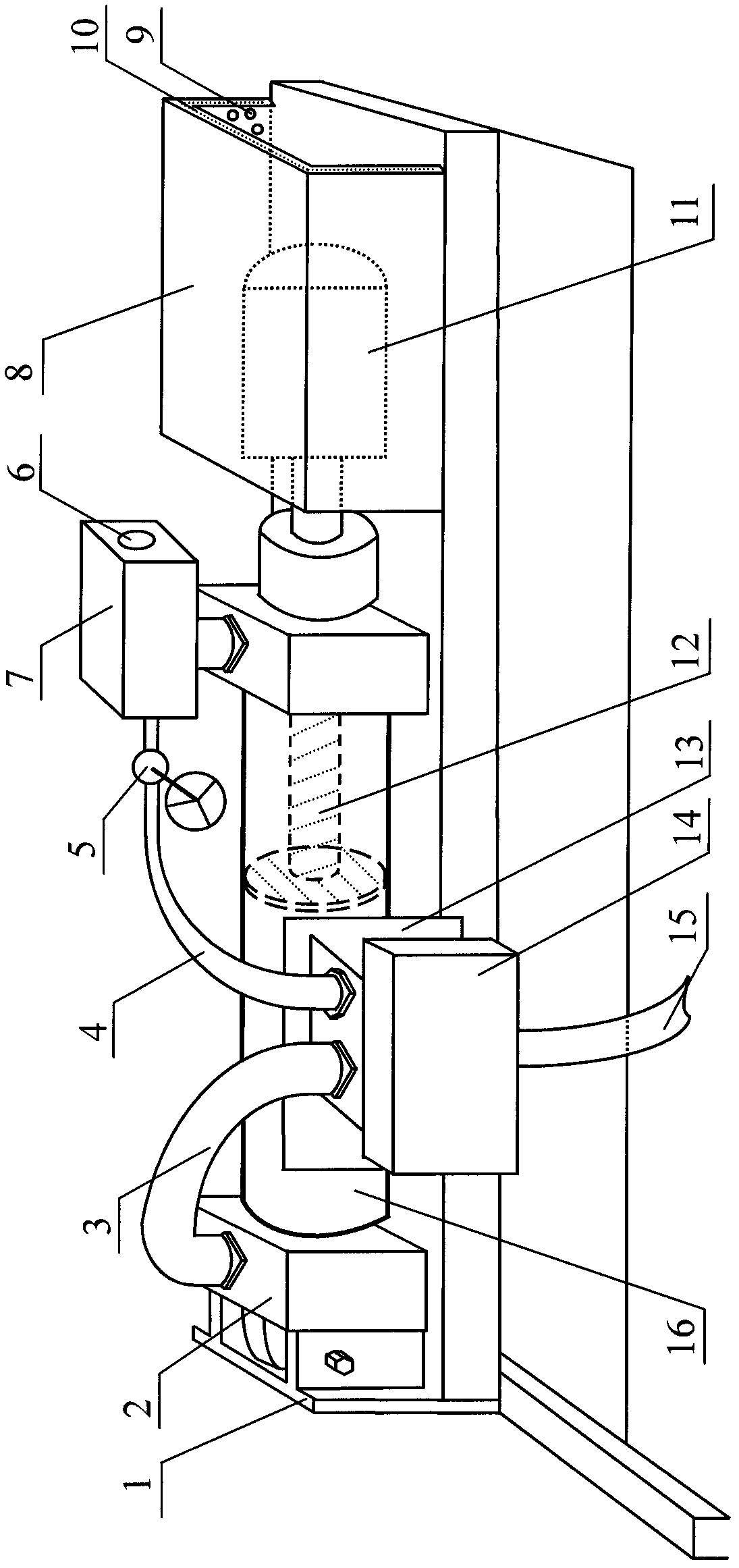
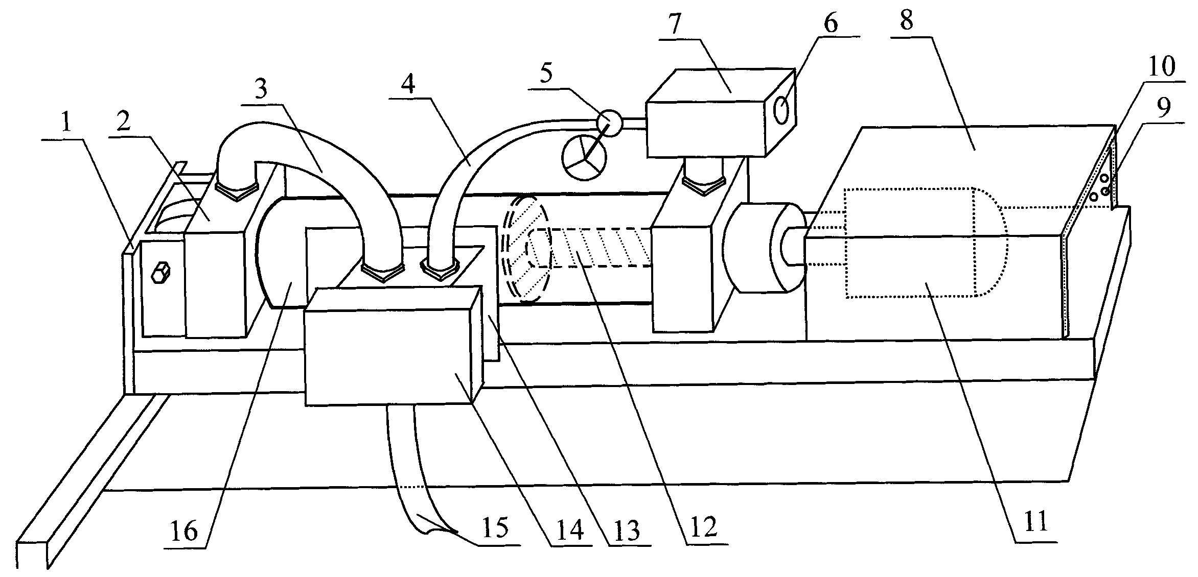
[0019] like figure 1 As shown, the present invention includes an electromagnetic reversing valve 14, a cylinder 16, a hammer 11, a quick exhaust valve 7 and the like.

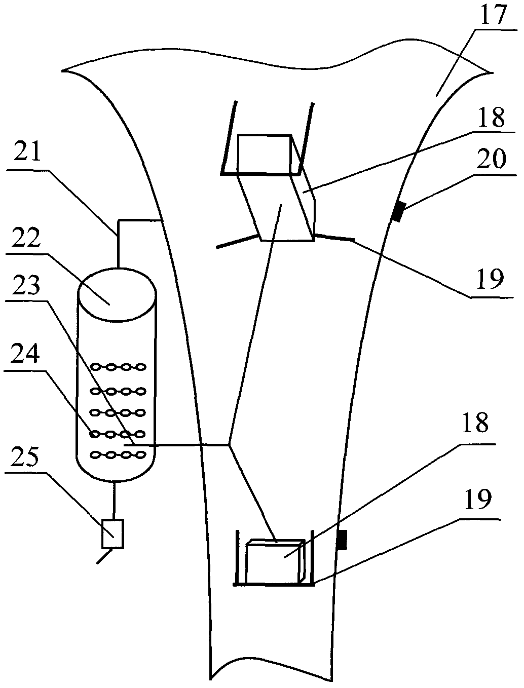
[0020] The cylinder 16 is fixed on the base 1 through the fixed seat 2, and the piston rod 12 is connected to the hammerhead 11 inside. The electromagnetic reversing valve 14 is connected to the air outlet pipeline 23 of the gas storage tank 22 through the intake pipeline 15, and is respectively connected to the two ends of the cylinder 16 through the front air pipe 3, the rear air pipe 4 and the quick exhaust valve 7, and the rear air pipe 4 and the quick exhaust valve. A regulating valve 5 is arranged between the air valves 7 . Adjusting the valve 5 can adjust the air intake, and then adjust the vibration amount when the tuplet 11 returns. That is, the valve 5 can be adjusted to open wide and open small to control the gas volume entering the cylinder 16 from the rear air pipe 4, so that the hammer head 11 c...


PUM


Abstract

The invention discloses a bunker wall vibration air hammer, which solves the problem of lower hopper-plugging dredging efficiency at present and is characterized by comprising an electromagnetic reversing valve, an air cylinder, a hammer head, a quick exhaust valve and the like, wherein the electromagnetic reversing valve is connected with an air outlet pipeline of an air storage tank through an air inlet pipeline, connected to one end of the air cylinder through a front air pipe and connected to the other end of the air cylinder through a rear air pipe and the quick exhaust valve; an adjustment valve is arranged between the rear air pipe and the quick exhaust valve; the air cylinder is fixed on a base; and a piston rod of the air cylinder is connected with the hammer head. The bunker wall vibration air hammer has a simple structure and low manufacturing cost; the whole device is arranged outside the wall of a hopper, so openings are not required to be formed on the hopper, the dredging capability is higher and the bunker wall vibration air hammer is quick and convenient to install and maintain; due to an electric control system, regular and continuous vibration can be realized and the vibration frequency can be set randomly; furthermore, the vibration strength is higher, can be adjusted and much higher than manual strength; the vibration is uniform and an effect is outstanding, so the working efficiency can be improved by multiple times; and the bunker wall vibration air hammer is particularly applicable to dredging of raw coal bunkers of thermal power plants.

Description

Technical field [0001] The invention belongs to a dredging device in the conveying process of solid particle materials, more precisely, it belongs to a device for clearing the clogging of a hopper and making the material conveying smooth. Background technique [0002] During the process of conveying powdery, granular, massive or mixed solid materials, due to the high humidity, high ash content and high viscosity of the material, the material will adhere to the silo wall or be blocked in the silo or cone. Bucket and other containers, or arching in the hopper, resulting in cut-off, affecting the normal and continuous production, especially often encountered in the process of transporting raw coal in thermal power plants. Due to the ash and moisture, the pressure of the upper coal can easily squeeze the raw coal into lumps, causing the coal hopper to stick to coal, canopy coal, form arches, and block coal, which will cause safety hazards and affect the power generation of the u...

Claims


Application Information

Patent Timeline
Patent Type & Authority Applications(China)
IPC IPC(8): B65D88/66
Inventor 赵东楼
Owner ANHUI KANGDI ELECTRIC POWER SCI & TECH
Why Eureka
Try Eureka