Turbulence forming appliance and heat exchanger and water heater using same

A technology for heat exchangers and water heaters, applied in heat exchange equipment, fluid heaters, fluid mixers, etc., which can solve problems such as gap corrosion of heat transfer tubes 4, difficulty in fluid circulation, and large flow path resistance

Active Publication Date: 2020-07-07
RINNAI CORP
View PDF6 Cites 0 Cited by
  • Summary
  • Abstract
  • Description
  • Claims
  • Application Information

AI Technical Summary

Problems solved by technology

[0006] Since the gap 30 is very small, the flow path resistance is large, and the fluid is difficult to circulate, so that the fluid stays in the gap 30, and because when foreign matter such as dust flows into and accumulates in the gap 30, the fluid is further trapped in the gap 30. internal stagnation, so the heat transfer tube 4 may have crevice corrosion from the part of the gap 30

Method used


Image

  • Turbulence forming appliance and heat exchanger and water heater using same
  • Turbulence forming appliance and heat exchanger and water heater using same
  • Turbulence forming appliance and heat exchanger and water heater using same

Examples


Embodiment Construction

[0045] The mode for carrying out the present invention will be described in detail with reference to the drawings.

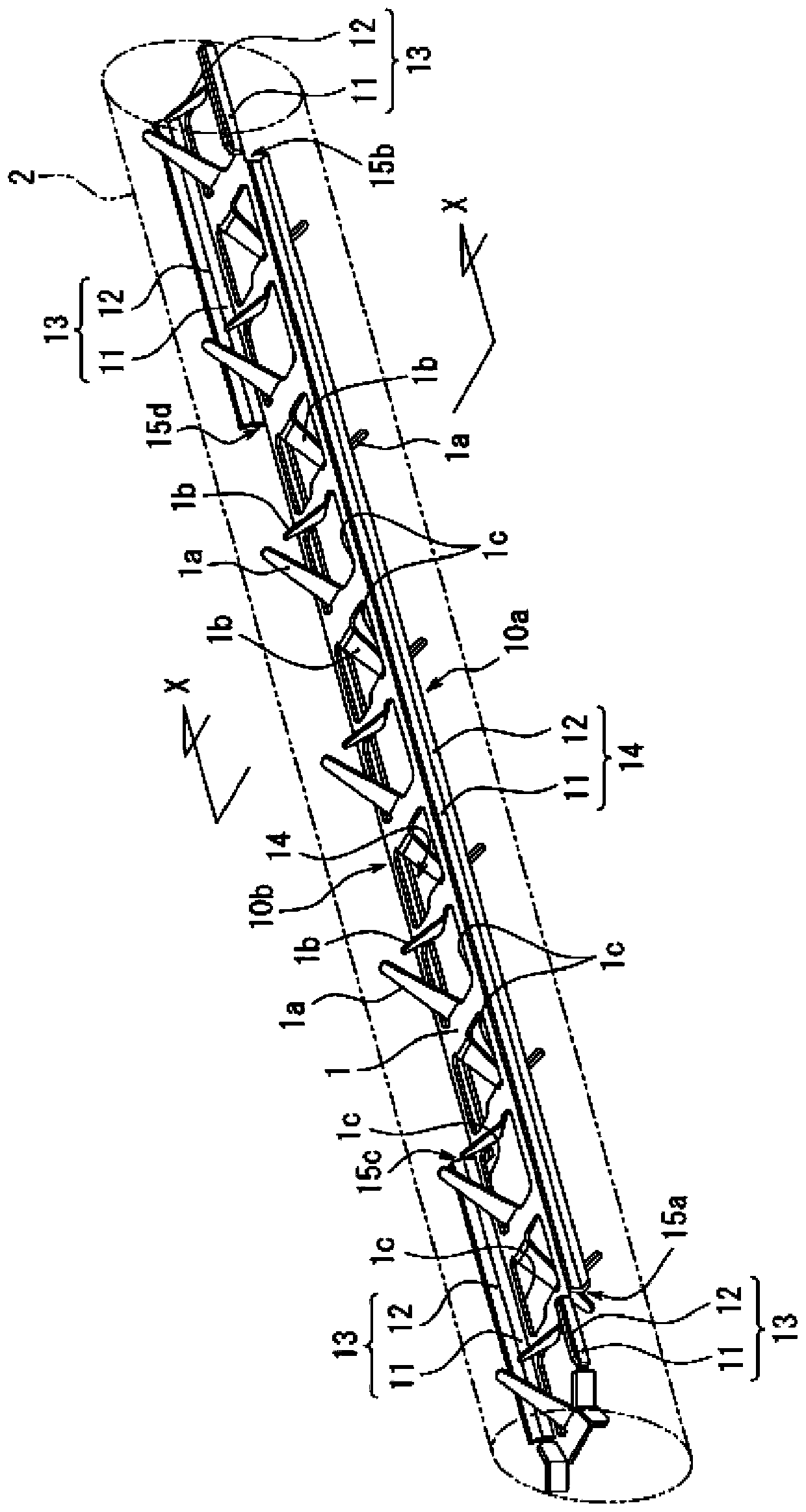
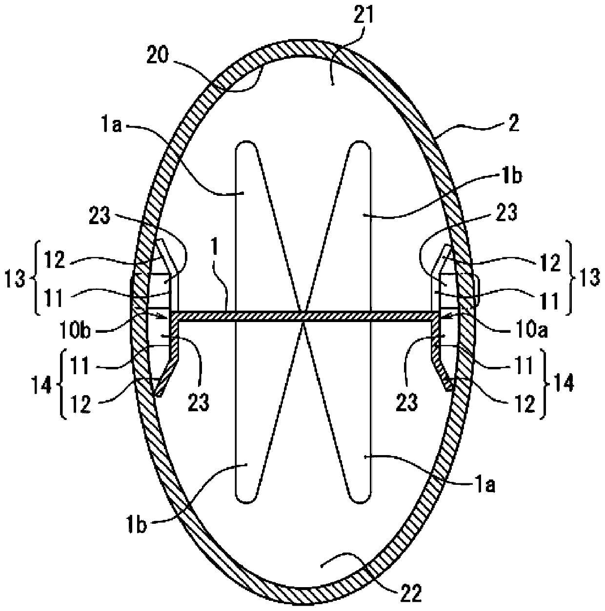
[0046] figure 1 It is a perspective view showing a state where the turbulent flow forming tool according to the first embodiment of the present invention is inserted into the heat transfer tube 2, figure 2 yes figure 1 Cross-sectional view of X-X.

[0047] The turbulent flow forming device of the first embodiment, such as figure 1 , figure 2 As shown, it is installed in the heat transfer tube 2 of the elliptical shape of the longitudinal section, and has a width that can be placed along the center line of the major diameter of the ellipse constituting the heat transfer tube 2 and is approximately consistent with the length of the heat transfer tube 2. Elongated flat part 1 constitutes. The plate part 1 can be made of stainless steel.

[0048]In the flat plate member 1, a plurality of through holes 1c consisting of cut holes and a plurality of protrudi...


PUM


Abstract

The object of the present invention is to prevent the fluid from stagnating in the gap formed between the turbulent flow forming device and the inner peripheral surface of the tube wall of the heat transfer tube so as not to cause crevice corrosion. The present invention provides a device for forming turbulent flow, which is inserted into a heat transfer tube (2) with a substantially elliptical cross-section along the direction of the flow path and has a plurality of protruding pieces (1a) (1b) protruding from its front and back sides. The flat plate member (1) is constituted, and at least one of the two sides (10a) (10b) of the flat member (1) along the direction of the flow path is provided with a The rotation prevention piece that is arranged in a manner and the front end is in contact with the inner peripheral surface (20) of the tube wall of the heat transfer tube (2) prevents the rotation of the flat plate member (1) in the heat transfer tube (2), and the rotation prevention piece and the rotation prevention piece A space (23) through which fluid can communicate is formed between the inner peripheral surfaces (20) of the pipe walls.

Description

technical field [0001] The present invention relates to a turbulent flow forming device inserted into a heat transfer tube in order to generate turbulence (turbulence) in a fluid flowing through the heat transfer tube, and a heat exchanger and a heat exchanger using the turbulent flow forming device. water heater. Background technique [0002] The heat transfer tubes constituting the heat exchanger are heated by the combustion exhaust gas of the gas burner to raise the temperature of the fluid inside. It is known that in order to suppress local boiling of the fluid in the heat transfer tube and promote heat exchange and improve thermal efficiency, a turbulent flow forming device for causing turbulence in the fluid in the heat transfer tube is inserted into the heat transfer tube (Japanese Patent Laid-Open Publication No. 11- 108458). [0003] As the device for forming the turbulent flow, for example, a device configured as follows, such as Figure 8 As shown, cutting holes...

Claims


Application Information

Patent Timeline
Patent Type & Authority Patents(China)
IPC IPC(8): F28F13/12
CPCF28F13/12F24H9/0026F28D21/0007F24H8/006Y02B30/00B01F25/43151B01F25/431974F28D1/053F24H9/0015F28D2021/0024F28F2250/102B01F25/4314
Inventor 根木英尚长坂敏充中越贵章
Owner RINNAI CORP
Why Eureka
Try Eureka