furniture hinge

A hinge and furniture technology, applied in the field of furniture hinges, can solve the problems of small main force, bending of the piston rod, and smooth door closing, etc., and achieve the effects of small friction, long life and moderate strength.

Active Publication Date: 2011-12-14
伍志勇
View PDF6 Cites 5 Cited by
  • Summary
  • Abstract
  • Description
  • Claims
  • Application Information

AI Technical Summary

Problems solved by technology

Because the cylinder body is fixed, the piston rod 23.1 only moves forward and backward. When the movable seat touches the piston rod (especially when the movable seat just touches the piston rod), the main force that really acts on the axis of the piston rod is very small, making the door close Unsmooth and prone to bending of the piston rod

Method used


Image

  • furniture hinge
  • furniture hinge
  • furniture hinge

Examples


no. 1 example

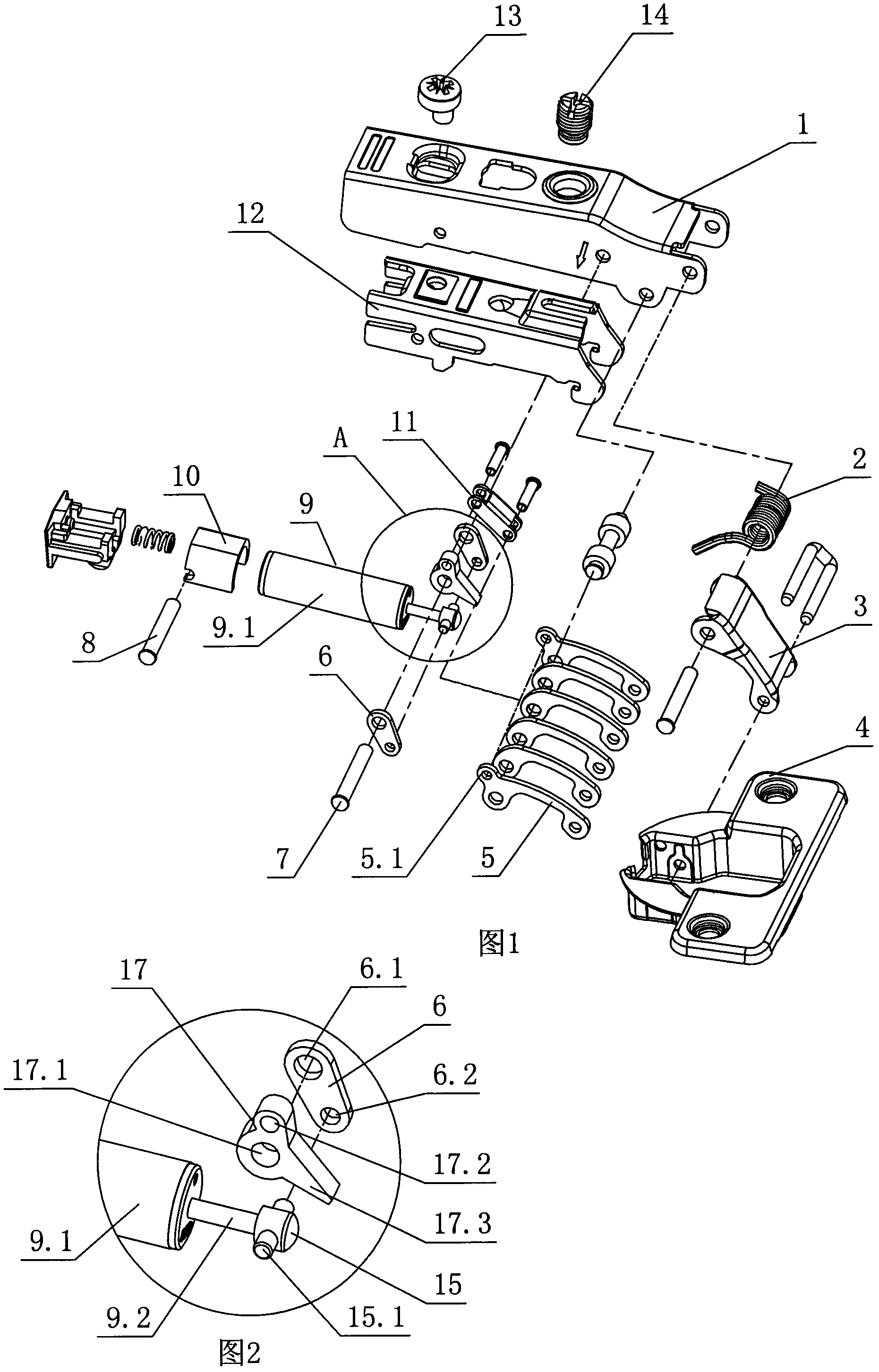
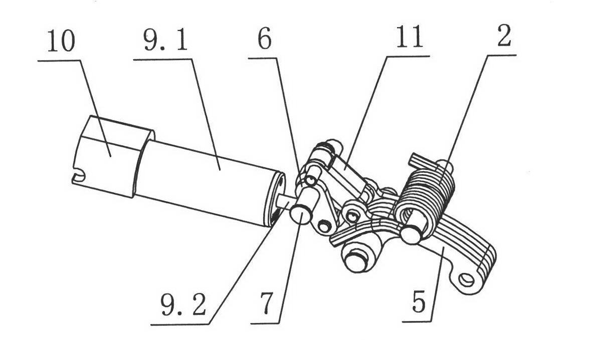
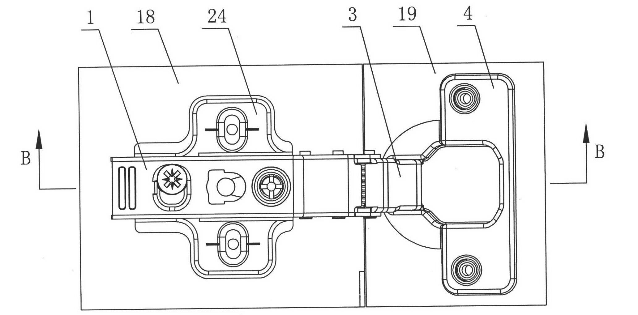
[0038] see Figure 1-Figure 7 , the furniture hinge includes a static member and a moving member that is in an active state relative to the static member during the hinge opening and closing process; the static member includes a connecting arm 1, and the connecting arm is provided with an automatic reset type damper that touches the moving member 9. One end of the automatic reset damper 9 is movably connected with the stationary member, and the other end is connected with the static member through a connecting piece; the connecting piece is respectively connected with the automatic reset damper and the static member in rotation.

[0039] The stationary component also includes a fixed arm 12, a fixed seat 24 and a component for connecting the stationary component and the moving component, which is preferably a pin 7; the fixed arm is connected to the inner side of the connecting arm 1 through the adjusting screw 14 and the eccentric wheel 13, and the connecting arm is fixed by ...

no. 2 example

[0051] see Figure 24 , the piston rod part 9.2' of the automatic reset damper points to the rear of the connecting arm, the end of the piston rod part is also provided with a hinge hole 9.4' to be rotatably connected with the connecting arm, and the cylinder part 9.1' is connected with the connecting arm through the connecting piece 6. The way in which the connecting piece 6 is connected with the cylinder body part 9.1' and the connecting arm may refer to the first embodiment. The structure of the connecting piece 6 can also refer to the various implementations introduced in the first embodiment.

[0052] The front end of the above-mentioned cylinder body part 9.1' can also be provided with a protrusion 9.5' to contact with the hinge moving member.

[0053] Other unmentioned parts are the same as those of the first embodiment.

no. 3 example

[0055] see Figure 25 , the transmission part of the contact block 77 and the inner rocker arm 25 are provided with intermeshing tooth patterns 77.1; Other unmentioned parts are the same as those of the first embodiment.


PUM


Abstract

A furniture hinge comprises an immobile member, and a movable member in a moving state with respect to the immobile member in the opening-closing process of the hinge, wherein the immobile member comprises a connecting arm in which an automatic resetting damper in contact with the movable member is arranged; one end of the automatic resetting damper is movably connected with the immobile member, while the other end of the automatic resetting damper is connected with the immobile member through at least one connecting element; and the connecting element is at least movably connected with the automatic resetting damper or the immobile member. The automatic resetting damper of the furniture hinge is arranged in the connecting arm in such a manner of slightly moving, so that the damper adapts to the contact point while contacting with the movable member of the hinge so as to slightly deflect and the acting force of the movable member mainly points to the direction of the axis of the damper. Simultaneously, the connecting element connected with the damper has no motion relationship with the movable member so that the opening and closing of the hinge is more smooth and more stable and the force is moderate; moreover, both ends of the damper are provided with connection points so as to ensure that the damper does not drop out of the connecting arm.

Description

technical field [0001] The invention relates to a furniture hinge, in particular to a furniture hinge equipped with an automatic reset damper. Background technique [0002] There are two types of dampers with cushioning hinges in existing furniture: one is a self-resetting damper, and its piston rod always has a force that sticks out. Assuming that the cylinder of the damper is fixed, when the piston rod is subjected to an external force that pushes it inward, a buffer is generated to resist the impact of the external force; when the external force is withdrawn, the piston rod can automatically extend again. The other is a non-automatic reset damper. The movement of the piston rod needs to be driven by an external force. When the external force is pulled or pushed, the piston rod produces a buffer; when the external force is withdrawn, the piston rod stops at the current position and cannot automatically return to the original position. state. [0003] Existing furniture h...

Claims


Application Information

Patent Timeline
Patent Type & Authority Applications(China)
IPC IPC(8): E05F3/20E05F3/04E05F5/06
CPCE05F5/006E05F5/02E05Y2201/21E05Y2201/264
Inventor 伍志勇
Owner 伍志勇
Why Eureka
Try Eureka