Heat sink for LED lamp and manufacturing method thereof

A technology of LED lamps and manufacturing methods, applied in lighting and heating equipment, cooling/heating devices of lighting devices, sustainable buildings, etc., can solve the problems of high production cost, material consumption, time-consuming, labor-intensive and material-consuming of radiators, and achieve Reduce the overall weight and material cost, increase the contact area, and enhance the effect of heat dissipation

Inactive Publication Date: 2011-12-14
伟业精密科技(惠州)有限公司
View PDF6 Cites 7 Cited by
  • Summary
  • Abstract
  • Description
  • Claims
  • Application Information

AI Technical Summary

Problems solved by technology

When manufacturing traditional LED light radiators, it is necessary to assemble the upper cover and the shell of the radiator after tapping. Adding the tapping process is not only time-consuming and laborious, but also causes waste of raw materials
Moreover, the heat sink of the LED lamp and the upper cover of the heat sink are bonded by thermally conductive adhesive, which increases material and labor costs
Moreover, manufacturers of heat sinks or LED lamps often use die-casting or machining to manufacture LED light heat sinks. The top cover of the heat sink and the shell of the heat sink made by die-casting are all substantial, which is expensive and bulky; Machining the upper cover of the heat sink and the shell of the heat sink requires removing the materials between the heat sink fins and inside the shell, which is time-consuming, laborious and material-intensive, resulting in high production costs and low production efficiency of the heat sink, which is not conducive to Improve the production efficiency of LED lamps

Method used


Image

  • Heat sink for LED lamp and manufacturing method thereof
  • Heat sink for LED lamp and manufacturing method thereof
  • Heat sink for LED lamp and manufacturing method thereof

Examples


Embodiment Construction

[0029] In order to facilitate the understanding of those skilled in the art, the present invention will be further described in detail below with reference to the drawings and embodiments.

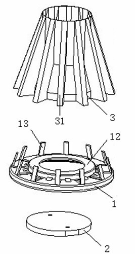
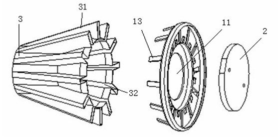
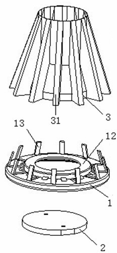
[0030]like figure 1 , 2 As shown, a radiator for an LED lamp includes a radiator cover 1, a radiator fin 2 for an LED lamp, and a radiator housing 3 with a central hole. The radiator housing 3 is provided with twelve cooling fins 31, Radiating body loam cake 1 is provided with circular heat sink mounting groove 11, and the shape of radiator housing and radiator loam cake is the common shape in the prior art, but radiator shell 3 and radiator loam cake 1 adopt It is formed by punching and stretching sheet coil material. The heat dissipation fins are folded from the shell wall of the heat dissipation body to form a hollow structure with a cavity 32 communicating with the central hole. Twelve heat dissipation fins are equidistantly arranged on the heat dissipation body shell. On the shell w...


PUM


Abstract

The invention relates to a heat dissipation body for a light emitting diode (LED) lamp, which is easy to manufacture and low in cost and has good heat dissipation effect. The heat dissipation body for the LED lamp is characterized in that: a heat dissipation body housing and a heat dissipation body upper cover are formed by stamping and stretching thin coil stocks; a plurality of heat dissipationfins are draped by the housing wall of the heat dissipation body housing to form a hollow structure with a cavity slot communicated with a central hole; the plurality of heat dissipation fins are distributed on the housing wall of the heat dissipation body housing at equal distances; a boss corresponding to the central hole is arranged in the middle of the bottom surface of the heat dissipation body upper cover; a positioning column corresponding to the cavity slot of each heat dissipation fin is arranged on the heat dissipation body upper cover; the positioning columns are inserted into the cavity slots of the corresponding heat dissipation fins; the heat dissipation body upper cover is riveted with the heat dissipation body housing; and an LED lamp heat dissipation sheet is embedded into an LED lamp heat dissipation sheet installation slot of the heat dissipation body upper cover in an interference fit manner. The invention also discloses a manufacturing method of the heat dissipation body of the LED lamp; and the heat dissipation body housing and the heat dissipation body upper cover are manufactured by stamping and stretching, so that the manufacturing method has the advantages of saving time and materials, effectively improving the production efficiency and reducing the production cost.

Description

technical field [0001] The invention relates to the technical field of heat dissipation for LED lamps, in particular to a radiator for LED lamps and a method for manufacturing the radiator for LED lamps. Background technique [0002] LED lamp heat sink is an important part of LED lamps. The heat dissipation effect of the heat sink directly affects the performance stability of the LED lamp. At the same time, the production cost of the heat sink also has a great impact on the production cost of the LED lamp. The LED lamp heat sink is usually composed of a heat sink upper cover, an LED lamp heat sink and a hollow heat sink shell, and a plurality of heat sink fins are arranged on the heat sink shell. The upper cover of the heat sink of the traditional LED light radiator and the housing are connected by threads or through connectors, and the heat sink of the LED light is pasted in the heat sink installation groove on the upper cover of the heat sink by thermally conductive glue. ...

Claims


Application Information

Patent Timeline
Patent Type & Authority Applications(China)
IPC IPC(8): F21V29/00F21V17/12F21Y101/02F21V29/77F21V29/83
CPCY02B20/72
Inventor 马从顺
Owner 伟业精密科技(惠州)有限公司
Why Eureka
Try Eureka