
Color filter substrate and display device

A technology for color filter substrates and display devices, applied in optics, nonlinear optics, instruments, etc., can solve the problems of poor display quality of display devices, affecting color display brightness, large light loss, etc., so as to improve display quality and improve The effect of color display brightness and specular reflectance

Inactive Publication Date: 2011-12-14
E INK HLDG INC
View PDF10 Cites 3 Cited by
  • Summary
  • Abstract
  • Description
  • Claims
  • Application Information

AI Technical Summary

Problems solved by technology

[0004] The structure of the black matrix 314 of the existing color filter substrate 300 has a light-shielding effect and can reduce light leakage (light leakage), but this structure will have a large light loss when used in a reflective display device
Moreover, in the process of light transmission, since the light has to be absorbed twice by the red photoresist 311, the green photoresist 312 and the blue photoresist 313 of the color filter substrate 300, the overall light intensity reflected by the display panel decreases, and the display The decrease in the overall light intensity of the device will affect the brightness of the color display, resulting in poor display quality of the display device

Method used


Image

  • Color filter substrate and display device
  • Color filter substrate and display device
  • Color filter substrate and display device

Examples


Embodiment Construction

[0025] In order to further explain the technical means and functions adopted by the present invention to achieve the intended purpose of the invention, the specific implementation, structure, characteristics and functions of the electronic device proposed according to the present invention will be described in detail below in conjunction with the accompanying drawings and examples. rear.

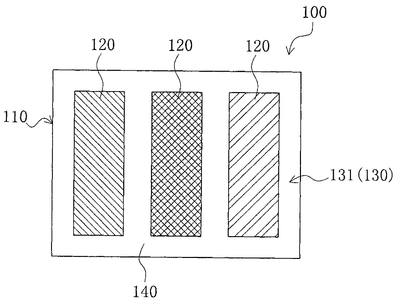
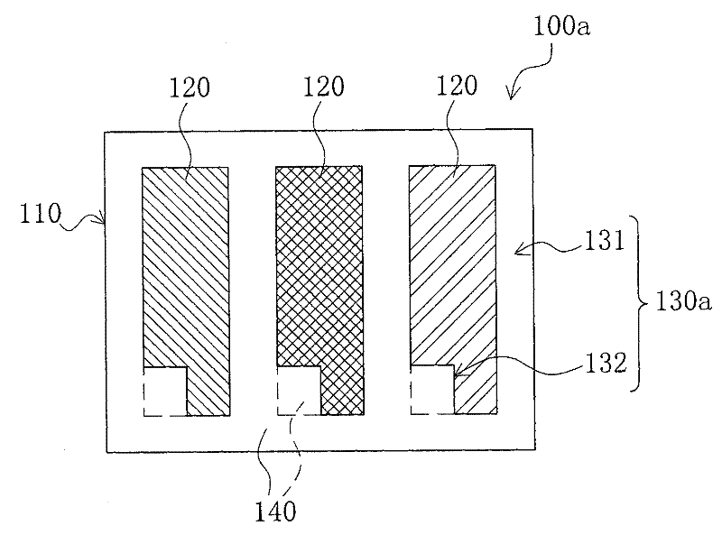
[0026] The color filter substrate includes a plurality of pixels. Since the structure of each pixel is substantially the same, in the following figures, one pixel of the color filter substrate will be used to represent the color filter substrate.

[0027] see figure 2 , figure 2 It is a schematic plan view of the structure of the color filter substrate in the first embodiment of the present invention. Such as figure 2 As shown, the color filter substrate 100 of this embodiment includes a transparent substrate 110, and a plurality of color photoresists 120 ( figure 2 Only the structur...


PUM


Abstract

The invention relates to a color filter substrate, which includes a transparent substrate, a plurality of color photoresist arranged on the transparent substrate and a high reflection area arranged on the transparent substrate. The high reflection area at least includes a first area separating each color photoresist, and the high reflection area is filled with reflective material or is a hollow area. The present invention also relates to a display device, which includes a lower substrate, a driving circuit layer arranged on the lower substrate, a display layer arranged on the driving circuit layer, and the above-mentioned color filter substrate arranged on the display layer. The high reflection area is beneficial to improve the reflection brightness of the display device, thereby improving the display quality of the display device.

Description

technical field [0001] The present invention relates to a display device, and in particular to a color filter substrate and a display device with the color filter substrate. Background technique [0002] The traditional electrophoretic display device is a black and white display device. In order to make the electrophoretic display device more competitive in the market, the existing technology uses a color filter substrate to make the electrophoretic display device achieve a color effect. The electrophoretic display device conforms to the current trend of colorization of the display device. [0003] Please refer to figure 1 , figure 1 It is a schematic cross-sectional view of an existing color filter substrate. Such as figure 1 As shown, the existing color filter substrate 300 includes a plurality of red photoresists 311, a plurality of green photoresists 312 and a plurality of blue photoresists 313 arranged on a transparent substrate 310, and these red photoresists 311, ...

Claims


Application Information

Patent Timeline
Patent Type & Authority Applications(China)
IPC IPC(8): G02F1/167G02F1/1335
Inventor 王以靓陈礼廷刘全丰
Owner E INK HLDG INC
Learn More