
High Current Carrying Connectors

An electric connector and current-carrying technology, which is applied in the direction of connection and connection device components, circuits, etc., can solve the problems of restricting the large capacity of the electronic communication industry and unfavorable normal operation of the system, so as to improve production efficiency and safety performance, Simple structure, low temperature appreciation effect

Inactive Publication Date: 2011-12-14
SHANGHAI AEROSPACE SCI & IND ELECTRIC APPLIANCE RES INST
View PDF4 Cites 2 Cited by
  • Summary
  • Abstract
  • Description
  • Claims
  • Application Information

AI Technical Summary

Problems solved by technology

However, the maximum rated current of the electrical connector in the prior art is 30A, and only when the working current is ≤30A can it guarantee normal operation, because the contacts of the electrical connector are only allowed to work normally under the condition of a temperature rise of 30°C, but The temperature rise value of the contact ≤ 30 ℃, its rated current is up to 30A, when the connector works to 50A, the temperature rise value of the test is as high as about 40 ℃, which is far greater than 30 ℃, which exceeds the industry's 30 ℃ for connectors The requirement of temperature rise brings more heat to the system, which is not conducive to the normal operation of the system, and greatly restricts the development of the electronic communication industry towards large-capacity and high-power systems

Method used

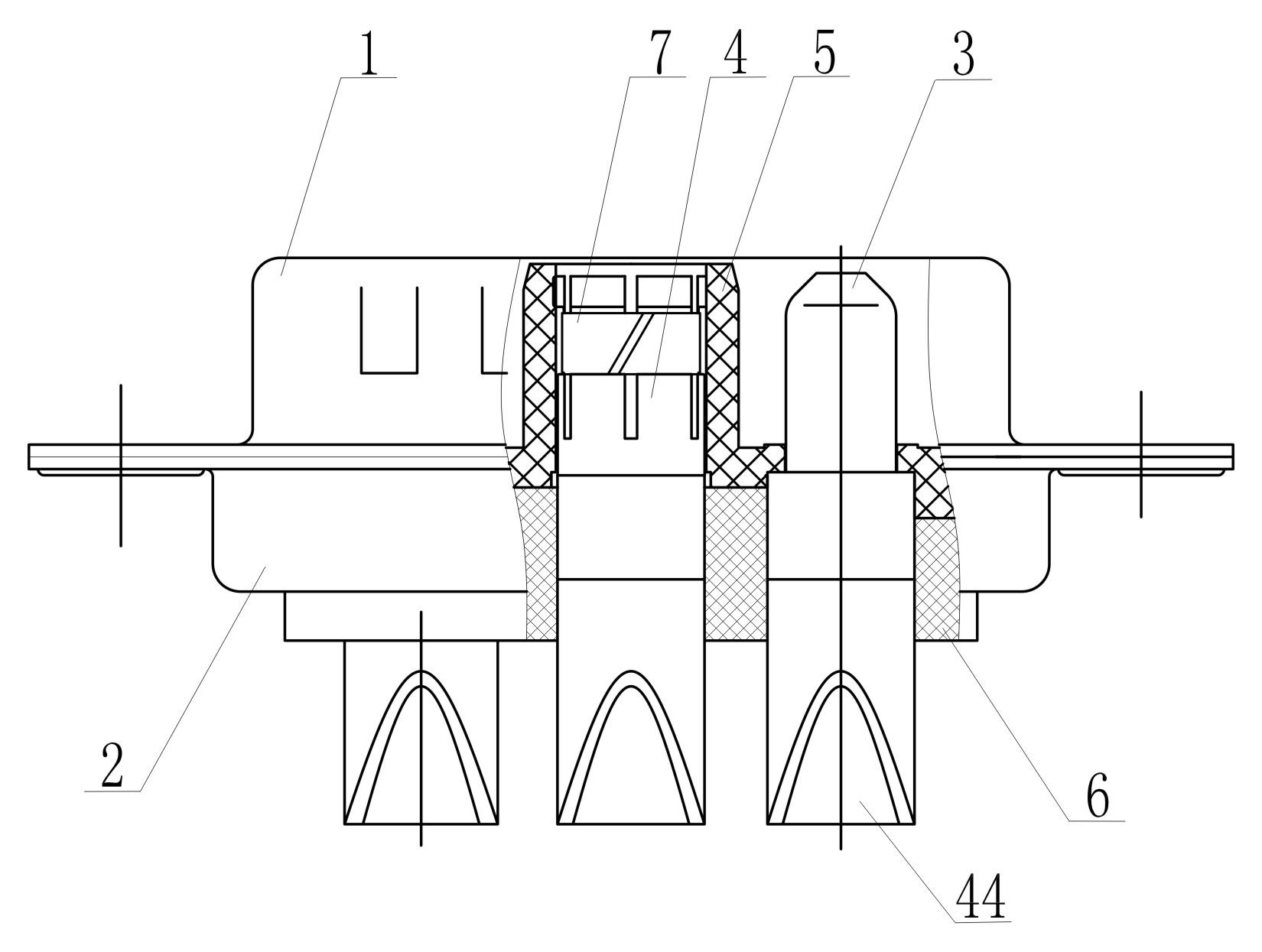
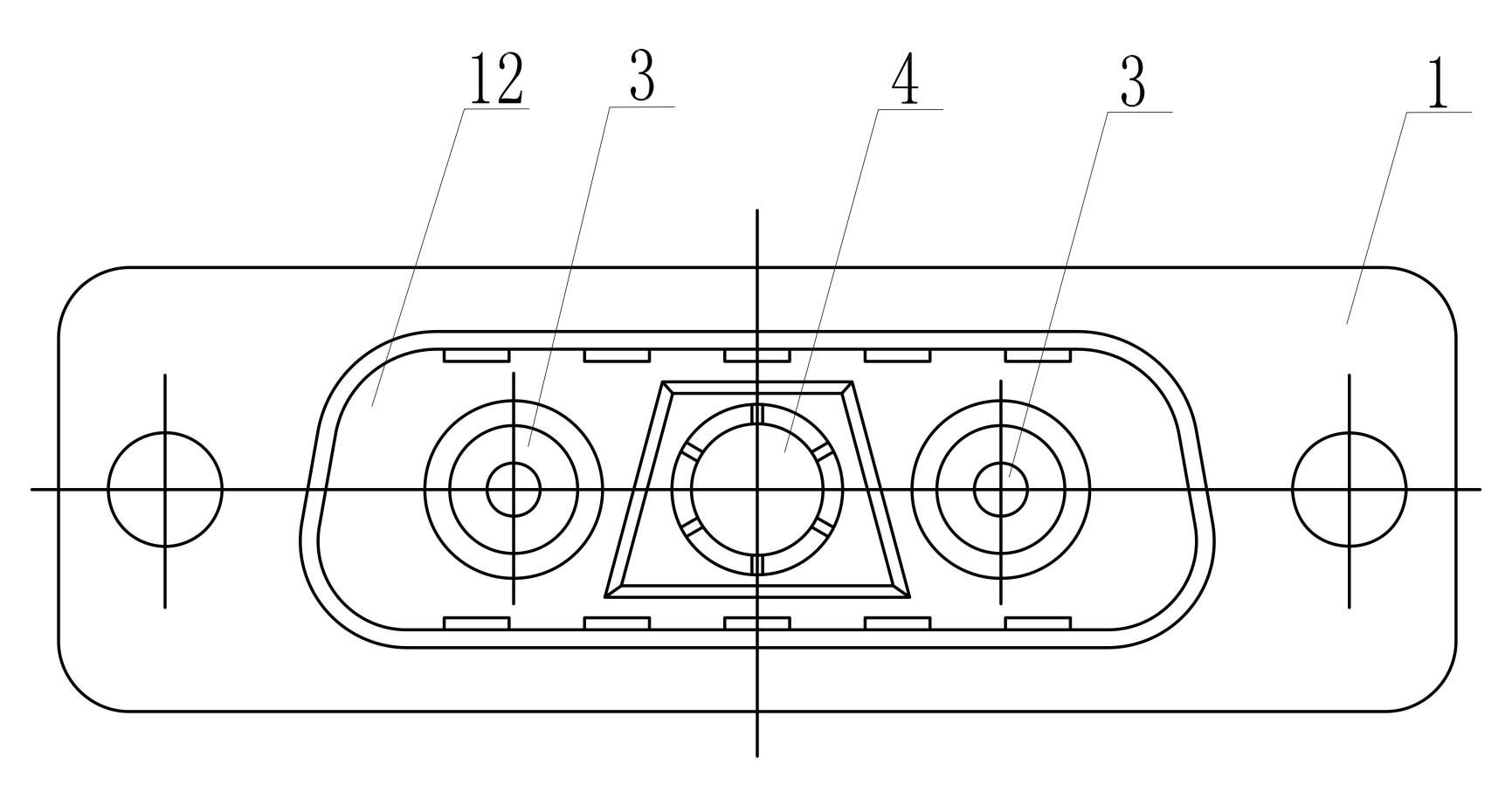
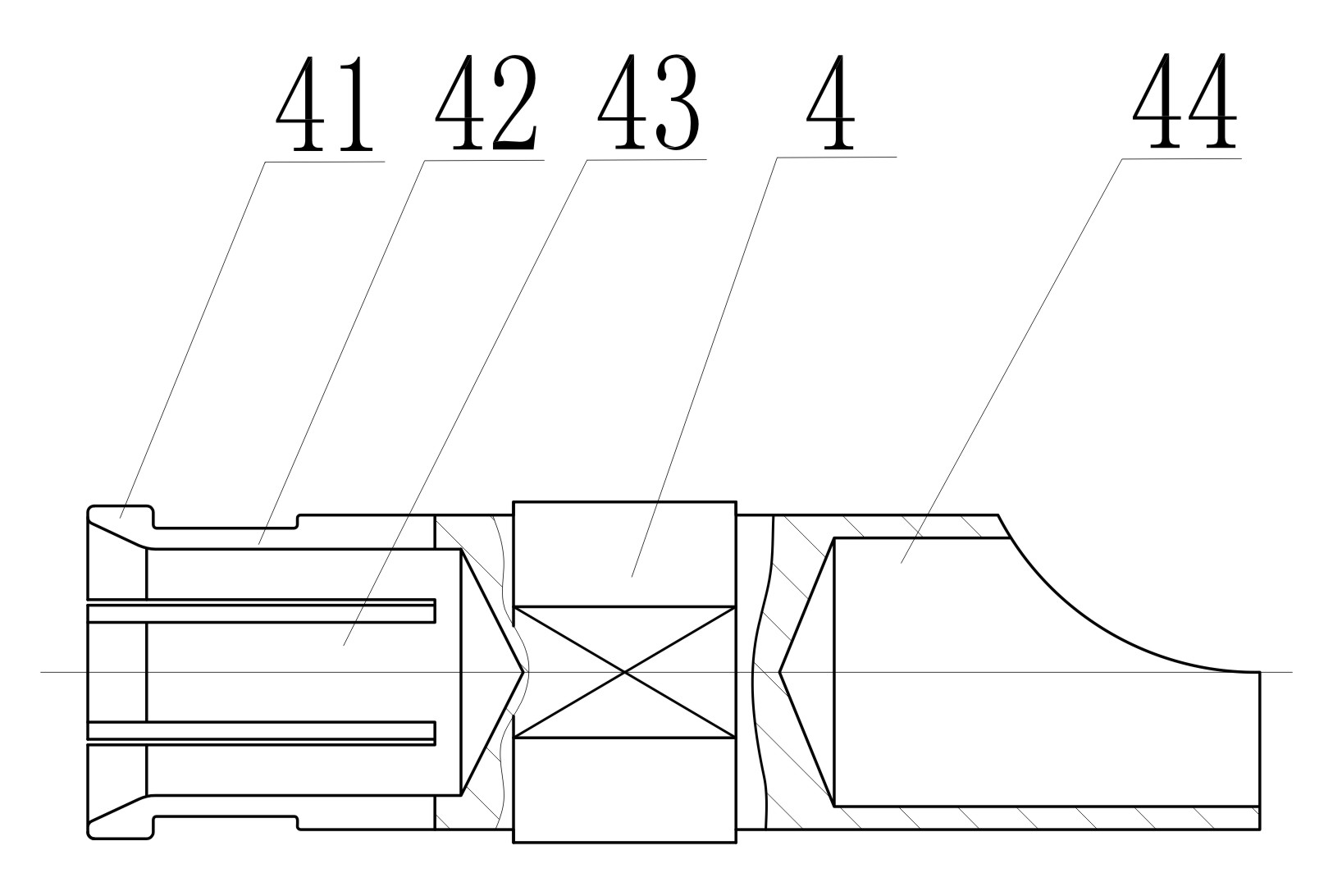

Image

  • High Current Carrying Connectors
  • High Current Carrying Connectors
  • High Current Carrying Connectors

Examples


Embodiment Construction

[0012] See attached figure 1 ~ attached figure 2 , the present invention consists of pins 3, sockets 4, upper end caps 1, and lower end caps 2 arranged on upper insulator 5 and lower insulator 6. 3 and the socket 4 are fixedly arranged on the upper and lower insulators 5 and 6, and the upper end cover 1 and the lower end cover 2 are fastened and sealed to form a rectangular electrical connector. After the upper end cover 1 and the lower end cover 2 are fastened, they are fastened by screws. The groove insertion hole 44 at one end of the pin 3 and the jack 4 is exposed outside the socket 12 of the lower end cover 2, and the plug 31 and the reed insertion hole 43 at the other end of the pin 3 and the jack 4 are exposed at the upper end. In the socket 12 of the cover 1.

[0013] See attached image 3 , one end of the jack 4 is a reed insertion hole 43, and the other end is an electrical contact piece of a groove insertion hole 44. The reed insertion hole 43 is made of telluri...


PUM


Abstract

The invention discloses a high-current-carrying electrical connector, which includes pins and sockets. There is an annular groove on the connection hole, and the port is provided with a punching bag structure, and a spring ring is clamped on the annular groove; one end of the pin is a needle-shaped plug, and the other end is an electrical contact with a groove socket hole; the pin The socket is fixedly arranged on the upper and lower insulators, and the upper and lower end covers are buckled and sealed to form an electrical connector. Compared with the prior art, the present invention has high current, low temperature rise, and good clamping force of the socket, which greatly meets the specification requirements of the connector working at a high load current of 50A, and the temperature rise is ≤30°C, and is especially suitable for electronic communication High current-carrying system connections in the field.

Description

technical field [0001] The invention relates to the technical field of electronic components, in particular to a high current-carrying electrical connector. Background technique [0002] In today's electronic communication fields, such as voice transmission, data transmission, image transmission, etc., the required signal propagation speed is getting faster and higher, the frequency is getting higher and higher, and the power is getting higher and higher. At the same time, the degree of systemization and integration Correspondingly, the use of electrical connectors is becoming more and more widespread. With the development of the electrical connector industry, more and more electrical systems require larger operating currents, and generally require More than 30A. However, the maximum rated current of the electrical connector in the prior art is 30A, and only when the working current is ≤30A can it guarantee normal operation, because the contacts of the electrical connector ...

Claims


Application Information

Patent Timeline
Patent Type & Authority Applications(China)
IPC IPC(8): H01R13/18H01R13/04H01R13/03H01R13/502
Inventor 王敏陈永生王华巍
Owner SHANGHAI AEROSPACE SCI & IND ELECTRIC APPLIANCE RES INST
Learn More