
Post-failure live treatment method for protection device of distribution network system and portable protection device

A protection device and system protection technology, applied in the direction of emergency protection circuit devices, circuit devices, electrical components, etc., can solve the problems of weak power grid operation mode and increased risk of power grid safe operation, and achieve the level of safe power grid operation without being affected and work. The effect of increased efficiency and simplified workflow

Active Publication Date: 2014-04-23
SUZHOU POWER SUPPLY OF JIANGSU ELECTRIC POWER +1
View PDF3 Cites 0 Cited by
  • Summary
  • Abstract
  • Description
  • Claims
  • Application Information

AI Technical Summary

Problems solved by technology

[0005] (1) It is necessary to perform a power outage operation for the primary equipment interval corresponding to the fault protection device, which is time-consuming and laborious, and the work efficiency is low;
[0006] (2). It is necessary to cut off the primary equipment corresponding to the fault protection device. If the power supply area is powered by a single power supply, the power users in the power supply area must face Power failure risk, power supply companies also face liability for breach of contract;
[0007] (3) It is necessary to cut off the power at the primary equipment interval corresponding to the fault protection device. If it is the interval of the tie line of the substation in the grid system, the grid operation mode is weak, and the grid Increased security risk

Method used


Image

  • Post-failure live treatment method for protection device of distribution network system and portable protection device
  • Post-failure live treatment method for protection device of distribution network system and portable protection device
  • Post-failure live treatment method for protection device of distribution network system and portable protection device

Examples


Embodiment Construction

[0025] Below in conjunction with accompanying drawing, preferred specific embodiment of the present invention is described:

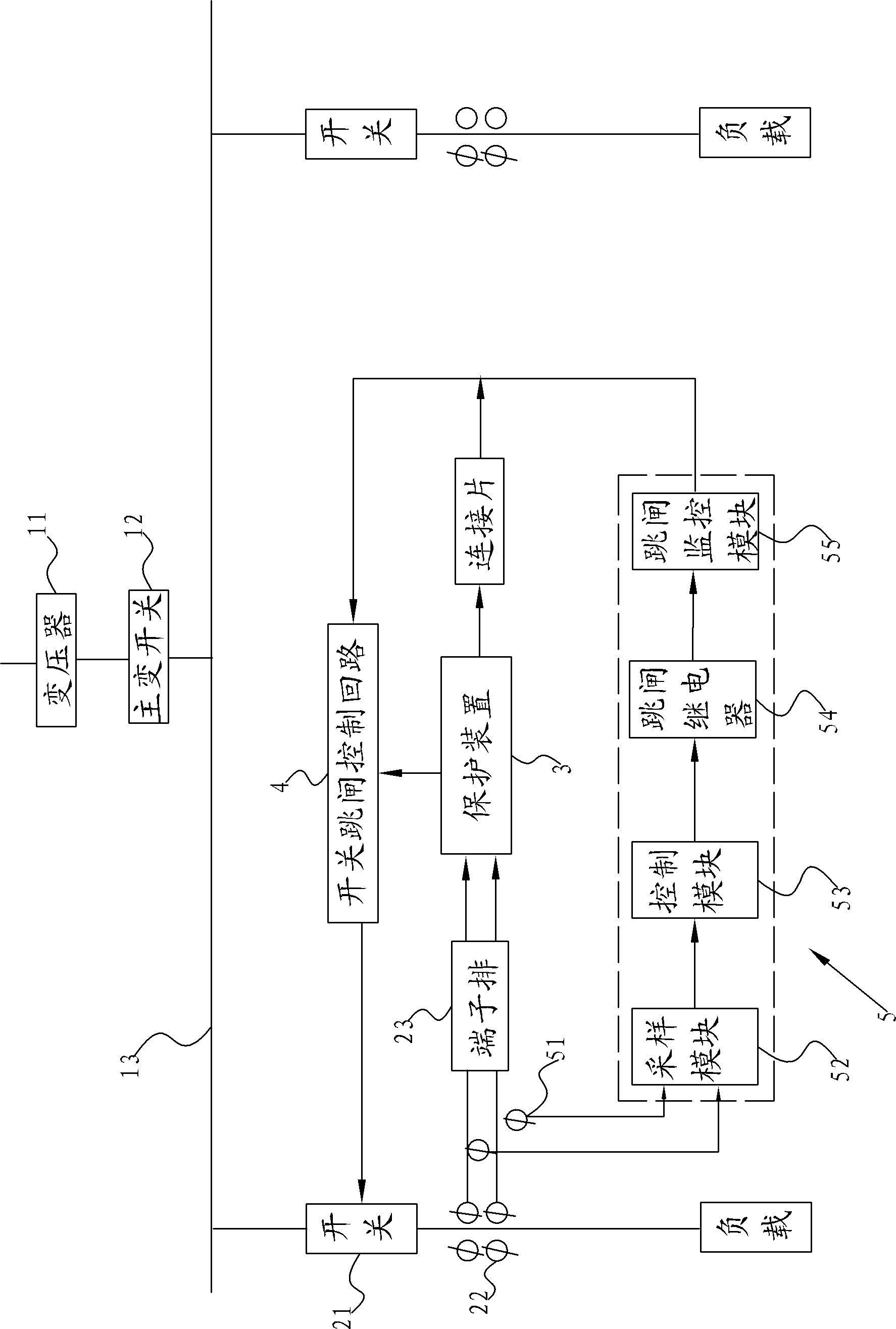
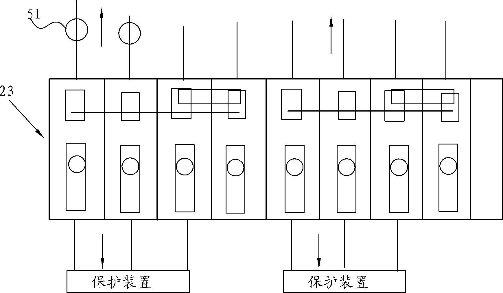
[0026] like figure 1 The distribution network system shown is mainly composed of a substation layer, a primary equipment interval layer, and a protection device. The interval layer includes several, which are mounted on the bus bar 13, and the output end is used to connect with the user load to realize power supply. Each primary equipment interval includes a switch 21, a current transformer 22 connected to the outlet of the switch 21 on the primary side, The secondary side of the current transformer 22 is connected to the protection device 3 through the terminal block 23, and a switch trip control circuit 4 is also provided between the protection device 3 and the switch 21. Under normal working conditions, the protection device 3 samples the current transformer. The current signal of 22 is compared with the set current value, if the current output...


PUM


Abstract

The invention relates to a portable protection device for post-failure live treatment of a protection device of a distribution network system and a live treatment method thereof, and the portable protection device comprises a current clamp clamped on the connection line between the secondary side of a current transformer and a terminal block, a sampling module for collecting current on the current lamp, a control module connected with the output end of the sampling module and a tripping relay connected with the output end of the control module, wherein the tripping relay is used for connecting with a switch tripping control loop, when failure occurs in the protection device, the tripping relay is put into the connection with the switch tripping control loop under drive of the control module so as to enable the portable protection device to replace the protection device for being put into operation temporarily. As live working treatment is adopted during one equipment interval corresponding to the failure protection device, the workflow is simplified, the working efficiency is improved and the safe operation level of a power grid is not affected.

Description

technical field [0001] The present invention relates to a charging processing method after a protection device fails in a distribution network system, in particular to using a portable protection device instead of the fault protection device to temporarily realize the basic protection function of the primary operating equipment corresponding to the fault protection device, thereby eliminating the need for specific The primary equipment takes power-off measures to carry out live treatment of the fault protection device. Background technique [0002] The power distribution system, especially for the voltage level system of 35KV and below, usually consists of a substation, a 10kV / 20kV / 35kV output busbar connected to the substation, and multiple primary equipment intervals mounted on the busbar. In order to monitor and protect primary The operation of the equipment interval, each primary equipment interval corresponds to a protection device, and the protection device itself ofte...

Claims


Application Information

Patent Timeline
Patent Type & Authority Patents(China)
IPC IPC(8): H02H7/22H02J13/00
Inventor 朱振亦周文华沈炯顾建林张曦黄文辉
Owner SUZHOU POWER SUPPLY OF JIANGSU ELECTRIC POWER
Learn More