A flexible anti-scouring surface protection system and its implementation method
An anti-scouring and flexible technology, applied in breakwaters, coastline protection, construction, etc., can solve the problems of high cost and high material cost, and achieve the effect of low cost, convenient construction and good collaborative adaptability
- Summary
- Abstract
- Description
- Claims
- Application Information
AI Technical Summary
Problems solved by technology
Method used
Image
Examples
Embodiment 1
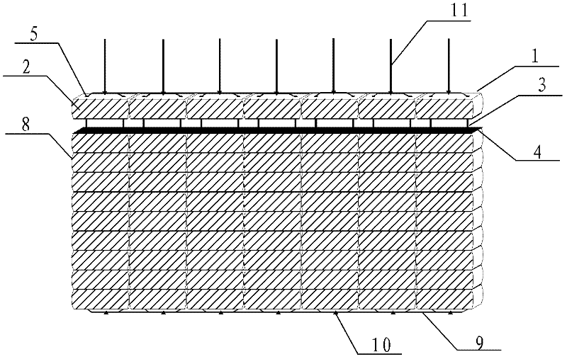
[0047] figure 1 It is a three-dimensional schematic diagram of the first embodiment of the flexible anti-scouring surface protection system of the present invention:
[0048] A flexible anti-scouring surface protection system, which is composed of several layers of bricks 1 arranged parallel to each other. Each brick layer is composed of several prefabricated bricks 2 of the same specification. The upper and lower brick layers 1 pass through the ropes 3 inside. Connected to each other, a flexible hinge isolation belt 4 is provided between two adjacent brick layers 1, and the flexible hinge isolation belt 4 is provided with a through hole for the rope 3 to pass through. The two sides of the prefabricated brick 2 are symmetrically processed with two rope holes 5 passing through the upper and lower sides. When multiple prefabricated bricks are stacked neatly, the left through hole of the upper brick is aligned with the left rope hole of the lower brick; The right rope hole of the br...
Embodiment 2
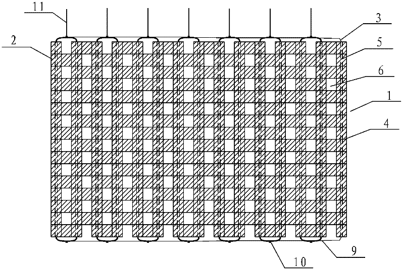
[0054] figure 2 It is a top view of the second embodiment of the flexible anti-scouring protective surface system of the present invention:
[0055] A flexible anti-scouring surface protection system. The system of prefabricated bricks 2 is similar to the system of prefabricated bricks 2 in Example 1. The prefabricated bricks 2 are stacked in a "product" shape. The two sides of the prefabricated bricks 2 are respectively Two rope holes 5 through the upper and lower sides are processed symmetrically. When a plurality of prefabricated bricks 2 are stacked neatly, the left rope hole of the upper brick is aligned with the right rope hole of the lower left brick; the right of the upper brick The rope hole is aligned with the left rope hole of the brick on the right side of the lower layer. After the rope 3 is passed through the rope hole 5, the prefabricated bricks 2 are linked in the shape of "product" to form a whole curtain. A green hole 6 is left between two adjacent prefabricat...
Embodiment 3
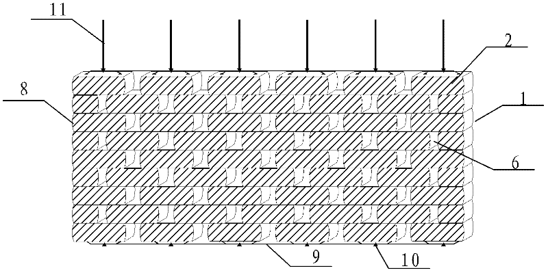
[0059] image 3 Yes figure 2 The three-dimensional structure diagram of an optimized implementation of Example 2 is shown. The structure is the same as the other structures of the example. The difference is that: First, the left and right sides of the prefabricated brick 2 are processed into convex arc-shaped end surfaces 8 , Avoiding mutual jamming or collision damage between adjacent prefabricated bricks 2; second, in this embodiment, the use of the flexible hinge spacer 4 is omitted, which further saves costs.
[0060] Other structures and descriptions are the same as in Example 2
PUM
 Abstract
Description
Claims
Application Information
 - R&D
- Intellectual Property
- Life Sciences
- Materials
- Tech Scout
- Unparalleled Data Quality
- Higher Quality Content
- 60% Fewer Hallucinations
Browse by: Latest US Patents, China's latest patents, Technical Efficacy Thesaurus, Application Domain, Technology Topic, Popular Technical Reports.
© 2025 PatSnap. All rights reserved.Legal|Privacy policy|Modern Slavery Act Transparency Statement|Sitemap|About US| Contact US: help@patsnap.com


