Air duct ignition burner

An ignition burner and burner technology are applied in the field of ignition devices of boilers, which can solve the problems affecting the normal use of the ignition burner, the burning loss of the ignition burner, the burning loss of the ignition air duct, etc., so as to achieve the burning loss of the ignition air duct and the combustion The effect of less self-burning loss, stable combustion and less self-burning loss

Inactive Publication Date: 2011-12-21
DONGFANG BOILER GROUP OF DONGFANG ELECTRIC CORP
View PDF5 Cites 5 Cited by
  • Summary
  • Abstract
  • Description
  • Claims
  • Application Information

AI Technical Summary

Problems solved by technology

[0004] However, during the operation of the air duct ignition burner, there are often problems such as unstable combustion, burning loss of the ignition air duct, and burning loss of the ignition burner itself, which affects the normal use of the ignition burner

Method used


Image

  • Air duct ignition burner
  • Air duct ignition burner
  • Air duct ignition burner

Examples


Embodiment 1

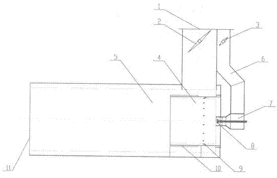
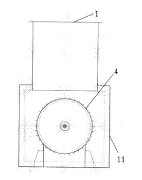
[0031] Example 1 as figure 1 and figure 2 As shown, the air duct ignition burner of the present invention includes an inlet air duct 1 and an outlet air duct 11, the inlet air duct 1 and the outlet air duct 11 are connected to each other, and are all connected to the hot primary air duct, and the outlet air duct The inner pre-combustion chamber 4 is arranged in the road 11, and an oil (gas) burner 7 is arranged in the said inner pre-combustion chamber 4. Of course, a plurality of them can be set according to actual needs. The oil (gas) burner 7 is provided with There are 8 burners. A burner air duct 6 is connected to the oil (gas) burner 7 , a burner baffle 3 is arranged in the burner air duct 6 , and a main air duct baffle 2 is arranged in the inlet air duct 1 . One end of the inner pre-combustion chamber 4 close to the oil (gas) burner 7 is circumferentially arranged with a plurality of wall-adhering air nozzles 9, and the wall-adhering air nozzles 9 communicate with the ...

Embodiment 2

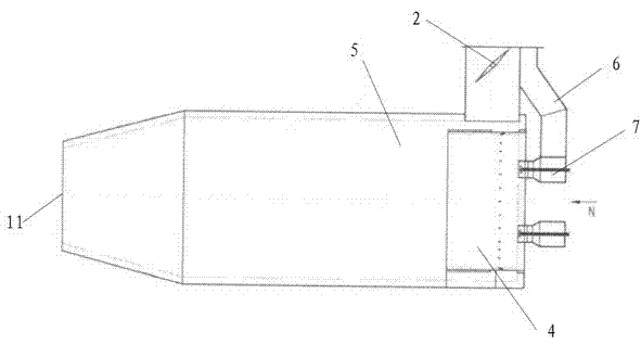
[0032] Example 2 as image 3 , Figure 4 and Figure 5 As shown, its structure is similar to that of Embodiment 1, the difference is that there are two oil (gas) burners 7, and of course there can be more than one according to actual needs. This embodiment is an ignition start-up system for a 300MW circulating fluidized bed, wherein the boiler is equipped with two air duct ignition burners, each air duct ignition burner is equipped with two oil burners, and the output of a single oil gun is 1900Kg / h.

[0033] The air duct ignition burner of the present invention has a simple structure and is easy to operate, and it has stable combustion during operation; the burning loss of the ignition air duct and the burner itself is small, and it can also be used as a non-combustion device for a preheating boiler; the structure is stable Reliable, not easy to be damaged by spontaneous combustion, long service life, and conducive to popularization.


PUM


Abstract

The invention discloses an air duct ignition burner, which belongs to the field of ignition devices. The air duct ignition burner of the present invention includes an inlet air duct and an outlet air duct, the inlet air duct and the outlet air duct (11) are connected to each other, and both are connected to the hot primary air duct, and the outlet air duct is provided with an inner A pre-chamber, at least one oil burner is arranged in the inner pre-chamber. The air duct ignition burner of the present invention has a simple structure and is easy to operate, and it has stable combustion during operation; the burning loss of the ignition air duct and the burner itself is small, and it can also be used as a non-combustion device for a preheating boiler; the structure is stable Reliable, not easy to be damaged by spontaneous combustion, long service life, and conducive to popularization.

Description

technical field [0001] The invention relates to an ignition device, in particular to an ignition device for a boiler. Background technique [0002] At present, China is the country with the largest number of circulating fluidized bed (CFB) boiler generator sets, the largest total installed capacity and the fastest development speed in the world. Circulating fluidized bed (CFB) boiler generator sets have been widely used in my country. [0003] The circulating fluidized bed (CFB) boiler generator set uses the circulating fluidized bed boiler as the power generation power. When starting the circulating fluidized bed boiler, it generally adopts the joint start mode of bed and bottom oil guns, mainly starting and igniting under the bed, and the ignition starts the system It is an important equipment for ignition start-up and low-load stable combustion of circulating fluidized bed (CFB) boilers. Air duct ignition burners are mainly used for under-bed ignition of circulating fluid...

Claims


Application Information

Patent Timeline
Patent Type & Authority Applications(China)
IPC IPC(8): F23D17/00
Inventor 张山鹰陈建红谢佳郭建平阳昔刚聂立苏虎陈建梅张定海
Owner DONGFANG BOILER GROUP OF DONGFANG ELECTRIC CORP
Why Eureka
Try Eureka