Reaction Flywheel Output Torque Measuring Circuit and Measuring Method

A technology of reactive flywheel and output torque, applied in measuring devices, torque measurement, power measurement, etc., to achieve the effect of improving calculation accuracy, simple design and high precision

Inactive Publication Date: 2011-12-21
HARBIN INST OF TECH
View PDF4 Cites 12 Cited by
  • Summary
  • Abstract
  • Description
  • Claims
  • Application Information

AI Technical Summary

Problems solved by technology

[0004] The purpose of the present invention is to solve the problem of measuring the output torque of the reaction flywheel during the dynamic test of the satellite attitude

Method used


Image

  • Reaction Flywheel Output Torque Measuring Circuit and Measuring Method
  • Reaction Flywheel Output Torque Measuring Circuit and Measuring Method
  • Reaction Flywheel Output Torque Measuring Circuit and Measuring Method

Examples


specific Embodiment approach 1

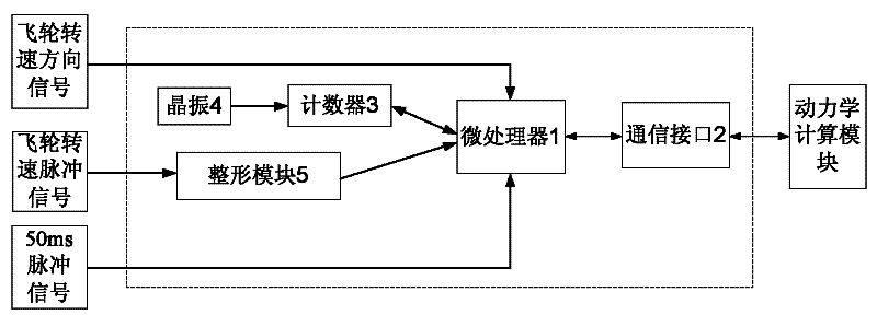
[0026] Specific implementation mode one: combine figure 1 Describe this embodiment, this embodiment comprises microprocessor 1, communication interface 2, counter 3, crystal oscillator 4 and shaping module 5; The first input and output end of microprocessor 1 is connected with the first output and input end of communication interface 2, The first input and output end of the microprocessor 1 is the communication input and output end, the second input and output end of the communication interface 2 is the signal input and output end of the dynamic calculation module, the second input and output end of the microprocessor 1 and the counter 3 The output and input ends are connected, the third input end of the microprocessor 1 is connected with the output end of the shaping module 5, the first input end of the microprocessor 1 is the flywheel speed pulse signal input end of the microprocessor 1, and the input end of the shaping module 5 end is the input end of the flywheel speed pul...

specific Embodiment approach 2

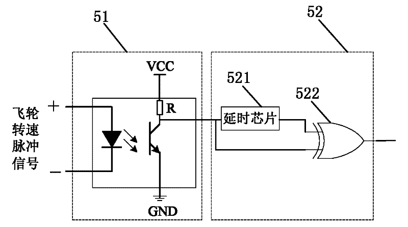
[0032] Specific implementation mode two: combination figure 2 Describe this embodiment, the difference between this embodiment and specific embodiment 1 is that the shaping module 5 includes a photoelectric isolation shaping chip 51 and a frequency multiplication processing circuit 52,

[0033] The input end of the photoelectric isolation shaping chip 51 is the input end of the flywheel speed pulse signal, and the output end of the photoelectric isolation shaping chip 51 is connected with the input end of the frequency multiplication processing circuit 52,

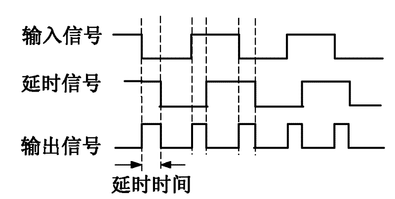
[0034] Frequency multiplication processing circuit 52 comprises delay chip 521 and XOR module 522, the input end of frequency multiplication processing circuit 52 is the input end of delay chip 521 and an input end of XOR module 522 simultaneously, the output end of delay chip 521 It is connected with the other input terminal of the exclusive OR module 522 , the output terminal of the exclusive OR module 522 is the output...

specific Embodiment approach 3

[0038] Specific embodiment three: the measurement method of the flywheel output torque of the present embodiment:

[0039]Microprocessor 1 initialization, set the interrupt trigger mode of the interrupt port of the flywheel speed pulse signal input terminal of microprocessor 1 to rising edge or falling edge trigger mode, that is, single edge trigger, set the interrupt of the 50ms pulse signal input terminal of microprocessor 1 The interrupt trigger mode of port is rising edge trigger; Microprocessor 1 defines the flywheel speed pulse interrupt count variable count and clears it; sets the internal timer of Microprocessor 1, the timing accuracy is 1ms, and starts timing;

[0040] Initialize counter 3, set the count of counter 3 to increase by 1 to represent 1 μs, start counter 3 to count; initialize 50ms interrupt update flag flag=0;

[0041] Set the priority of the 50ms pulse interrupt handler to be higher than that of the flywheel speed pulse interrupt handler;

[0042] The 5...


PUM


Abstract

The invention provides a reaction flywheel output torque measuring circuit and a measuring method thereof and relates to the field of measurement on output torque of a reaction flywheel, and solve the circuit and method provided by the invention can be used for solving the problems in measuring the output torque of the reaction flywheel in the calculation process of a dynamical model. The microprocessor of the circuit is connected to a communication interface, a counter and an integral module, and acquires a flywheel rotating speed direction signal and a 50ms pulse signal; the integral moduleacquires a flywheel rotating speed pulse signal; the counter is further connected to a crystal oscillator; and the communication interface outputs the signals of a dynamical calculation module. The method comprises the following steps of: initializing the microprocessor and the counter, wherein 50ms pulse interruption is superior to flywheel rotating speed pulse interruption; performing the 50ms pulse interruption: recording T50, setting flag to be equal to 1 and quitting the interruption; and performing the flywheel rotating speed pulse interruption: 1, adding 1 to the count value, performing a step 2 if the flag is equal to 1, otherwise, quitting the interruption; 2, reading Tflag, and calculating the rotating speed of the reaction flywheel within a current calculation cycle; 3, calculating moment; and 4, sending the moment to the dynamical model and quitting the interruption. The circuit and method disclosed by the invention are applied to dynamically testing a satellite attitude control system.

Description

technical field [0001] The invention relates to the field of measuring the output torque of a reaction flywheel. Background technique [0002] The reaction flywheel is a control component commonly used in small satellites, especially high-precision three-axis stable small satellites. Different output torques can be obtained through different input voltage inputs. It has the characteristics of high control precision, long life, and continuous control. When a satellite with a reaction flywheel is used for electrical testing, especially when performing a closed-loop test of an attitude control system or a mock-fly test, it is necessary to accurately measure the output torque of the reaction flywheel for the dynamic model calculation of the closed-loop test. Reaction flywheels commonly used in China generally output speed and speed direction signals. The speed is represented by the number of pulses per unit time, which is a TTL level square wave signal, and the speed direction i...

Claims


Application Information

Patent Timeline
IPC IPC(8): G01L3/00
Inventor 李化义张迎春李冬柏耿云海李璟璟
Owner HARBIN INST OF TECH
Why Eureka
Try Eureka