
Optical body, wall member, building fitting, and solar shading device

An optical body and optical layer technology, applied in the field of optical bodies that diffusely reflect incident light, can solve the problems of aggravation of heat island phenomenon and inability of grass to grow, and achieve the effect of inhibiting heat island phenomenon, inhibiting intensification, and inhibiting the appearance of diffraction patterns

Active Publication Date: 2015-02-11
DEXERIALS CORP
View PDF8 Cites 0 Cited by
  • Summary
  • Abstract
  • Description
  • Claims
  • Application Information

AI Technical Summary

Problems solved by technology

In urban areas, this causes the problem that the heat island phenomenon is exacerbated and grass cannot grow in areas illuminated by this reflected light

Method used


Image

  • Optical body, wall member, building fitting, and solar shading device
  • Optical body, wall member, building fitting, and solar shading device
  • Optical body, wall member, building fitting, and solar shading device

Examples


no. 1 approach

[0042] 1. First Embodiment (wherein the optical film is a wavelength selective film having diffuse reflection capability)

[0043] 2. The second embodiment (wherein the optical film is a semi-transmissive film with diffuse reflection capability)

no. 3 approach

[0044] 3. Third embodiment (wherein the optical film includes a light scatterer)

no. 4 approach

[0045] 4. Fourth embodiment (wherein the optical film includes a self-cleaning effective layer)

[0046] 5. Fifth embodiment (wherein the diffuse reflective surface is formed by using beads)


PUM

PropertyMeasurementUnit
surface roughnessaaaaaaaaaa
storage modulusaaaaaaaaaa

Abstract

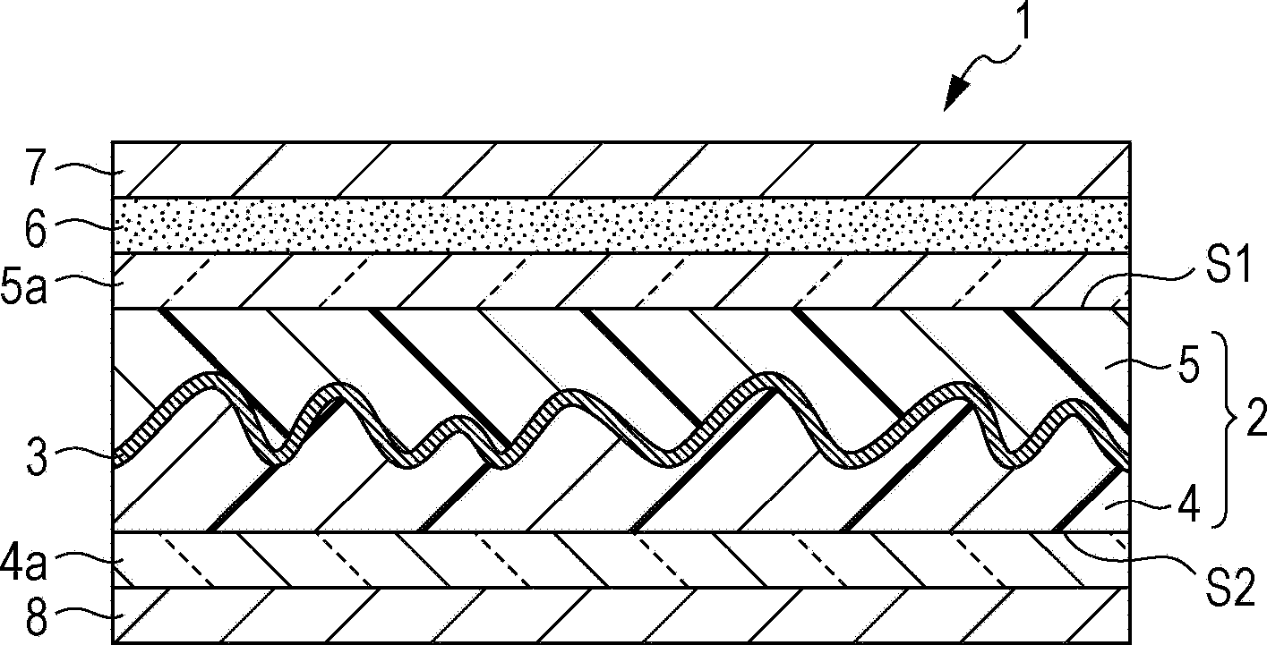
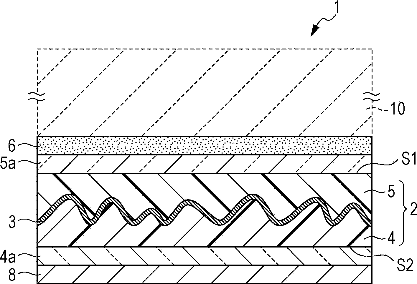
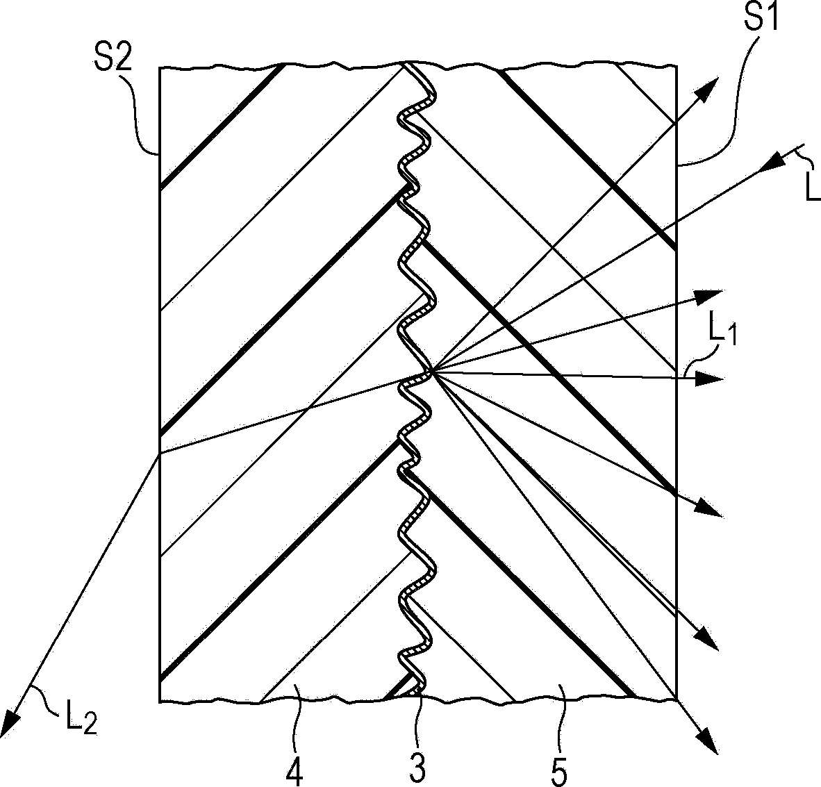
An optical body includes a first optical layer having a random concave-convex surface, a reflecting layer formed on the concave-convex surface, and a second optical layer formed on the reflecting layer to embed the concave-convex surface, wherein the reflecting layer is a wavelength-selective reflecting layer for diffusely reflecting, of incident light, light in a specific wavelength band and transmitting light other than the specific wavelength band therethrough.

Description

technical field [0001] The invention relates to optical bodies, wall elements, building fittings and sun protection devices. More specifically, the present invention relates to optical bodies for diffusely reflecting incident light. Background technique [0002] There is a window film for shading on the market in consideration of reducing the air conditioning load. Films for reflecting sunlight are also marketed as an example of shading technology. To manufacture the thin film, various methods have been disclosed which employ optical multilayer films, metal-containing films, transparent conductive films as reflective layers (see, for example, International Publication No. 05 / 087680). [0003] However, this type of reflective layer is formed on flat window glass, and incident sunlight is only specularly (regularly) reflected. Thus, light from the sky and reflected by the mirror of the flat window glass reaches other nearby buildings and the ground outdoors, where it is abs...

Claims


Application Information

Patent Timeline
Patent Type & Authority Patents(China)
IPC IPC(8): G02B5/26G02B5/02G02B1/10B32B3/30E06B9/24E06B9/386E06B9/42B32B7/02E06B5/00G02B5/08G02B5/23G02B5/28
CPCE06B9/386G02B5/208E06B9/24E06B9/28E06B9/40G02B5/0205G02B5/26G02B5/0289E06B2009/2417
Inventor 长浜勉谷岛胜行榎本正
Owner DEXERIALS CORP
Learn More