
A Redundant Excitation Double Armature Winding Multiphase Flux Switching Motor with Fault Tolerant Teeth

A double-armature winding and flux switching technology, which is applied to the shape/style/structure of windings, electric components, and winding conductors, can solve the problem that single-motor systems cannot guarantee reliability requirements, cannot meet acceleration performance and maximum speed, Increased motor size and system mass, etc., to improve reliability and fault-operating capability, overcome non-adjustable permanent magnetic field, and compact structure

Active Publication Date: 2011-12-21
SOUTHEAST UNIV
View PDF5 Cites 23 Cited by
  • Summary
  • Abstract
  • Description
  • Claims
  • Application Information

AI Technical Summary

Problems solved by technology

The current conventional single-motor drive system cannot well solve the contradiction between the torque-speed characteristics of the motor and the power demand of the system
If the power is constant, the acceleration performance and maximum speed requirements cannot be met; if the system dynamic performance is pursued, the motor power must be increased, which increases the motor volume and system mass
More importantly, the single-motor system cannot guarantee reliability requirements and enhanced fault-tolerant operation capabilities
Using a multi-motor combination structure will lead to a complex structure of the entire power system, large volume, and high cost

Method used


Image

  • A Redundant Excitation Double Armature Winding Multiphase Flux Switching Motor with Fault Tolerant Teeth
  • A Redundant Excitation Double Armature Winding Multiphase Flux Switching Motor with Fault Tolerant Teeth
  • A Redundant Excitation Double Armature Winding Multiphase Flux Switching Motor with Fault Tolerant Teeth

Examples


Embodiment Construction

[0021] The present invention will be further described below in conjunction with the accompanying drawings.

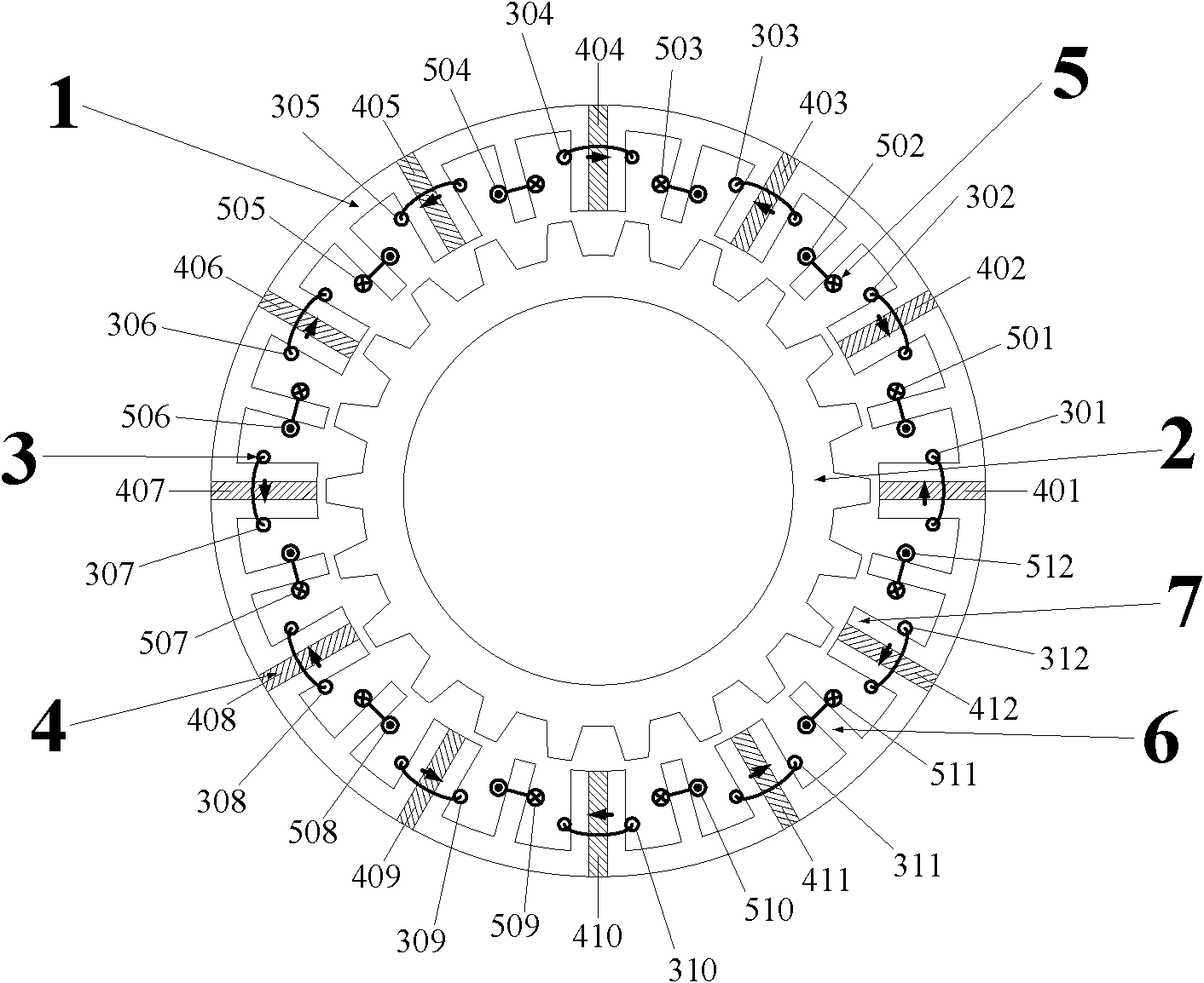
[0022] Such as figure 1 Shown is a redundant excitation dual armature winding multi-phase flux switching motor with fault-tolerant teeth, specifically a dual three-phase stator 24-slot / rotor 22-pole motor, the number of phases of the motor is m, the number of stator slots for P s , the number of rotor poles is P r ; where m=3.

[0023] The motor comprises a stator core 1, a rotor core 2 located in the stator core 1, 4m armature coils 3 and 4m field coils 5, the stator core 1 and the rotor core 2 are salient pole structures; the stator core 1 is composed of 4m E-shaped iron core units and 4m permanent magnets 4 for magnetization are staggered and spliced. The magnetization direction of the permanent magnets 4 is tangential, and the magnetization directions of adjacent permanent magnets 4 are opposite. The E-shaped The protruding teeth in the middle of the core unit ...


PUM


Abstract

The invention discloses a redundant excitation double-armature winding multiphase magnetic flux switching motor with fault-tolerant teeth, which comprises a stator core, a rotor core, 4m armature coils and magnetic exciting coils, wherein the stator core is formed by splicing 4m E-shaped iron core units and 4m permanent magnets in a staggering way; the magnetizing directions of the permanent magnets are tangential; the adjacent magnetizing directions are opposite; a raised tooth in the middle of each E-shaped iron core unit is a stator fault-tolerant tooth; raised teeth at both sides of each E-shaped iron core unit are permanent magnet teeth; one permanent magnet and two permanent magnet teeth which are in contact with the permanent magnet form a stator permanent magnet tooth; the armature coils are sheathed on the stator permanent magnet tooth; the 2m adjacent armature coils form a first set of symmetrical m-phase armature winding; the other 2m armature coils form a second set of symmetrical m-phase armature winding; the magnetic exciting coils are sheathed on a stator fault-tolerance tooth; and the magnetic exciting coils are sequentially connected in series from the head to thetail to form a set of single-phase central excitation winding. Compared with the prior art, the motor has the advantages that the fault tolerance and reliability of the motor are increased and the motor is provided with multiple operating modes.

Description

technical field [0001] The invention relates to a motor, in particular to a redundant excitation double armature winding multi-phase magnetic flux switching motor with fault-tolerant teeth. Background technique [0002] The current single-phase or three-phase motors adopt a structure in which the excitation and armature windings are placed separately, including the rotating excitation electric excitation structure where the rotor places the field winding / the stator places the armature winding, and the rotor places the permanent magnet / stator. Rotary excitation permanent magnet structure of armature winding, rotating armature electric excitation structure of stator placing excitation winding / rotor placing armature winding, rotating armature permanent magnet structure of stator placing permanent magnet / rotor placing armature winding. Except for the rotating permanent magnet excitation type, the above four structures require brushes and (or) commutators, which reduces the relia...

Claims


Application Information

Patent Timeline
IPC IPC(8): H02K1/14H02K1/17H02K3/46H02K3/28
Inventor 花为张淦程明
Owner SOUTHEAST UNIV
Learn More