A self-excited push-pull converter

A self-excited push-pull, converter technology, applied in the conversion equipment, instruments, DC power input converted to DC power output, etc., which can solve the problem of easy burnout, complicated circuits, and the circuit cannot be restored to normal by itself. Working status and other issues, to achieve the effect of good short-circuit protection performance consistency, easy debugging, and good self-protection ability

Active Publication Date: 2011-12-21
MORNSUN GUANGZHOU SCI & TECH
View PDF4 Cites 30 Cited by
  • Summary
  • Abstract
  • Description
  • Claims
  • Application Information

AI Technical Summary

Problems solved by technology

[0016] 2. Once there is a short circuit at the output, the circuit stops vibrating, and the two push-pull transistors are in the off state; after the output overcurrent and the short circuit disappear, the circuit cannot return to the normal working state by itself
[0018] 3. image 3 , Figure 4 , Figure 5 In the existing Jensen circuit, when the output is over-current or short-circuited, the transistors TR1 and TR2 generate a lot of heat...

Method used


Image

  • A self-excited push-pull converter
  • A self-excited push-pull converter
  • A self-excited push-pull converter

Examples


Embodiment 3

[0098] The working principle of embodiment three is:

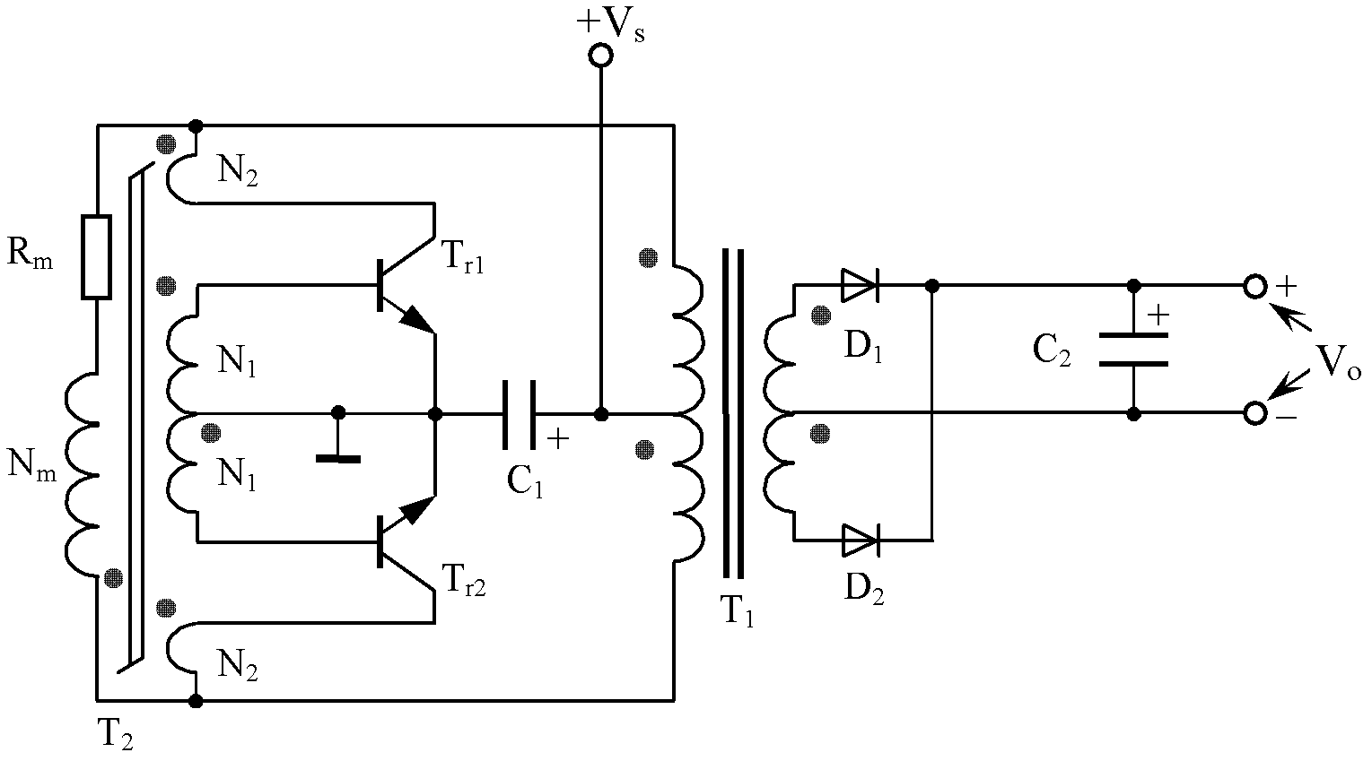
[0099] In normal operation, the capacitive reactance of the capacitor Cb is relatively large, and the resistor Rm plays a major role, and the circuit still works in the self-excited push-pull mode controlled by the magnetic saturation transformer T2.

[0100] When the output is short-circuited, as in the first embodiment, due to the effect of the two-terminal network 1, the circuit enters the high-frequency self-excited oscillation mode. At this time, the main transformer T 1 Also because the transmission efficiency is lower, the loss caused by the short circuit of the secondary side is converted to the main transformer T 1 The primary side is not large, so that the circuit does not vibrate, and the operating current of the circuit can be controlled in a lower range, which can also achieve the purpose of the present invention.

[0101] In the third embodiment, a capacitor or Figure 11-2 , Figure 11-3 , Figure 11-4 ,...


PUM


Abstract

The invention discloses a self-excitation push-pull type converter which comprises a Jensen circuit and is mainly characterized in that a two-terminal network with electric performance of accessing high frequency and stopping low frequency is formed between one end of magnetic saturation transformer primary winding in the Jensen circuit and one terminal of main transformer primary winding, namely the magnetic saturation transformer primary winding is connected in parallel with the main transformer primary winding through the two-terminal network. The self-excitation push-pull type converter disclosed by the invention has good self-protective capability, and can automatically recover normal work after disappearance of over-current and short circuit.

Description

technical field [0001] The invention relates to a self-excited push-pull converter, in particular to a self-excited push-pull converter used in industrial control and lighting industries. Background technique [0002] The existing self-excited push-pull converter, the circuit structure part comes from the self-excited oscillating push-pull transistor single-transformer DC converter invented by G.H.Royer in the United States in 1955, usually referred to as the Royer circuit, which also realizes high-frequency conversion. The beginning of the control circuit; in 1957, Jen Sen in the United States (Jen Sen, translated as "Jing Sen" in some places) invented the self-excited push-pull double transformer circuit, which was later called the self-oscillating Jensen circuit and the self-excited push-pull Jensen circuit. It is also known as Jingsen circuit; these two circuits are called self-excited push-pull converters by later generations. [0003] The self-excited push-pull conver...

Claims


Application Information

Patent Timeline
IPC IPC(8): H02M3/337H02M1/32
CPCH02M1/32H02M3/33538H02M3/3382H02M3/337Y02B70/10
Inventor 王保均
Owner MORNSUN GUANGZHOU SCI & TECH
Why Eureka
Try Eureka