
A Cascaded Non-Output Transformer Co-phase Power Supply System

A technology of power supply system and transformer, which is applied in the direction of output power conversion device, conversion equipment without intermediate conversion to AC, conversion of AC power input into AC power output, etc., which can solve the problem of capacitor voltage imbalance, rise or fall, input and output The power cannot guarantee the balance and other problems, so as to achieve the effect of expanding the working range

Inactive Publication Date: 2011-12-21
SOUTHWEST JIAOTONG UNIV
View PDF4 Cites 15 Cited by
  • Summary
  • Abstract
  • Description
  • Claims
  • Application Information

AI Technical Summary

Problems solved by technology

[0007] However, when the diode clamped multilevel converter transmits active current, the input and output power of each capacitor cannot be balanced, which will cause the voltages of different capacitors to rise or fall gradually, that is, the so-called unbalanced capacitor voltage problem occurs

Method used


Image

  • A Cascaded Non-Output Transformer Co-phase Power Supply System
  • A Cascaded Non-Output Transformer Co-phase Power Supply System
  • A Cascaded Non-Output Transformer Co-phase Power Supply System

Examples


Embodiment Construction

[0027] The present invention will be described in further detail below in conjunction with the accompanying drawings and specific embodiments.

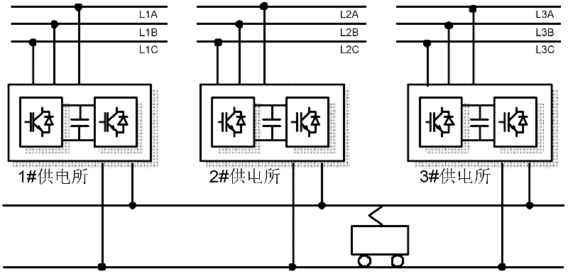
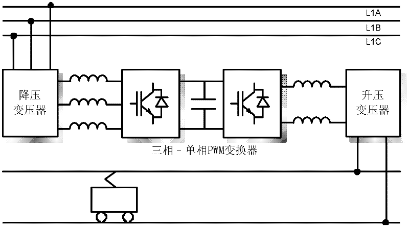
[0028] figure 2 It is a schematic structural diagram of the in-phase power supply system of the cascaded non-output transformer through-through mode of the present invention. The system is mainly composed of image 3 The three-phase-single-phase PWM converter and step-up / step-down transformer are shown. The converter absorbs active current from the three-phase AC side and transforms it into DC, and then outputs single-phase AC voltage through a single-phase inverter to provide reactive and active currents for traction loads. Since both the three-phase rectifier and the single-phase inverter can operate in four quadrants, the three-phase-single-phase PWM converter can balance and distribute the active current of the three-phase side system at the same time, while controlling the voltage frequency, phase and amplitude of the output si...


PUM


Abstract

The invention discloses a cascaded non-output transformer in-phase power supply system. The system is mainly composed of a power electronic conversion device cascaded with more than one three-phase-single-phase AC-DC-AC converter. The cascaded power electronic conversion device is directly connected to the traction catenary. Through the multi-module cascaded structure, the improvement The voltage level of the output converter is improved, so the output transformer can be eliminated. Since the output voltage amplitude, phase, and frequency can be controlled, the catenaries of adjacent substations can be directly connected to form a through traction power supply network. The present invention proposes a three-phase-single-phase converter structure suitable for arbitrary level diode clamping circuits. The structure includes a DC voltage stabilizing and equalizing auxiliary circuit, which can be realized under any power factor condition, especially when transmitting active current. The goal of voltage equalization and voltage regulation of each DC capacitor ensures that active power transfer or reactive power output can be achieved under any modulation depth.

Description

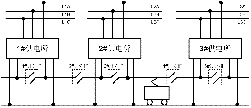
technical field [0001] The invention relates to an electrified railway power supply system, in particular to the technical field of traction network equipment without excessive phase division. Background technique [0002] There are problems of power quality and excessive phase separation in my country's current electrified railway power supply system and its technology. At present, the operation mode of electrified railway traction power supply system is mainly two-phase (out-of-phase) power supply. Compared with the three-phase power system, the increase of traction power of high-speed and heavy-duty trains makes the problem of negative sequence more prominent, and the reactive power in power quality is harmonious. Problems such as waves are also more serious. In addition, the loss of train speed and traction caused by electrical phase separation seriously affects the overall performance of the traction power supply system. [0003] figure 1 It is a traditional split-ph...

Claims


Application Information

Patent Timeline
IPC IPC(8): H02M5/44H02M5/458H02M3/07
Inventor 舒泽亮李群湛解绍锋陆可
Owner SOUTHWEST JIAOTONG UNIV
Learn More