High-voltage excitation constant-current power supply system

A power supply system and excitation technology, which is applied in the field of high-voltage excitation constant current power supply system, can solve the problems of tube performance deterioration, steady current tube temperature rise, and steady current tube power consumption, etc., to achieve volume and weight reduction and avoid power consumption. Loss, the effect of improving the utilization rate

Inactive Publication Date: 2013-05-08
中国地质科学院地球物理地球化学勘查研究所
View PDF5 Cites 0 Cited by
  • Summary
  • Abstract
  • Description
  • Claims
  • Application Information

AI Technical Summary

Problems solved by technology

[0004] 1. The voltage regulating transformer adopts a fixed tap method, and the number of voltage adjustable gears is small, which reduces the flexibility of field construction;
[0005] 2. The variable loss (copper loss) of the transformer is relatively large, and the utilization rate of the high-power power supply is low;
[0006] 3. Due to the use of transformers, the volume and weight of the entire constant current power supply system are large;
[0007] 4. Under high power conditions, it is difficult to achieve high power steady current power supply
When the power of the constant current power supply system reaches hundreds of kW, the power consumption of the steady current tube is greater, resulting in a rapid rise in the temperature of the steady current tube, deterioration of the performance of the tube, and a decrease in reliability, which can easily cause damage to the steady current tube
Therefore, under the condition of high voltage and high current, it is difficult to realize high-power constant-current power supply based on conventional constant-current supply technology solutions

Method used


Image

  • High-voltage excitation constant-current power supply system
  • High-voltage excitation constant-current power supply system
  • High-voltage excitation constant-current power supply system

Examples


Embodiment Construction

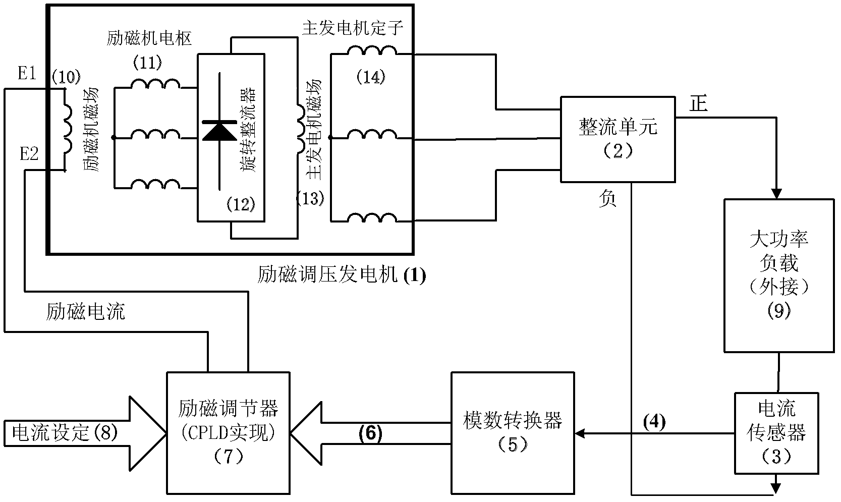
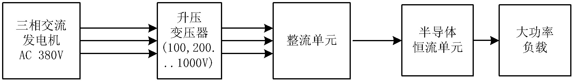
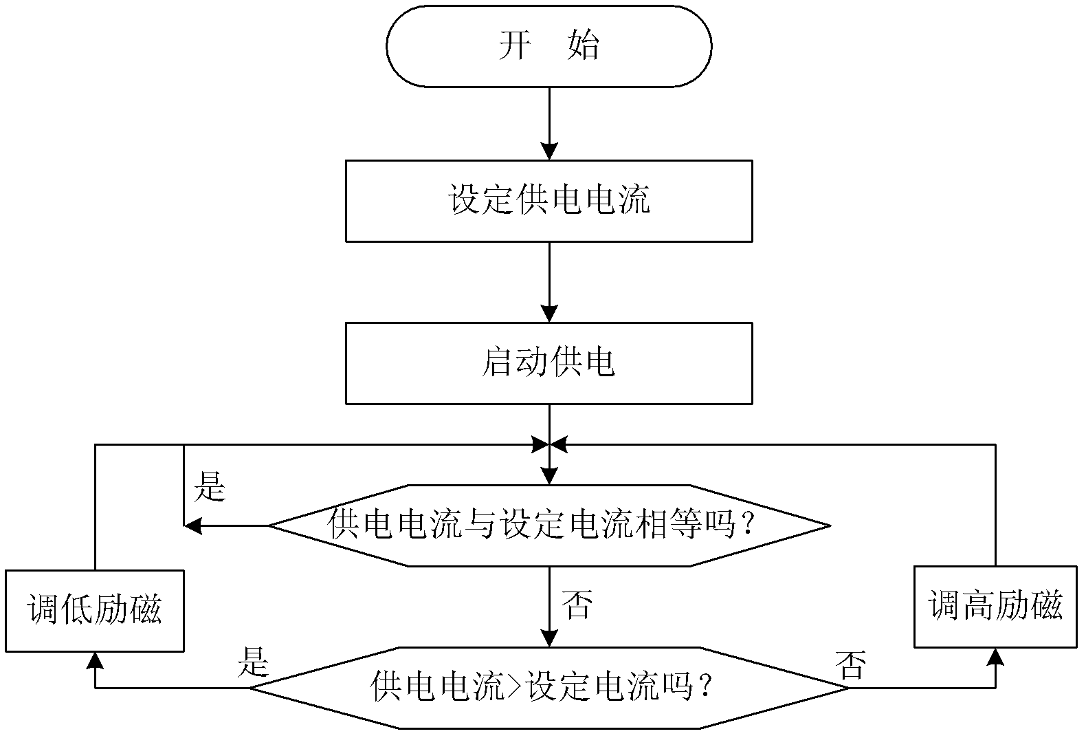
[0031] The invention relates to a high voltage excitation constant current power supply system. It uses an excitation voltage regulating generator and an excitation regulator to replace the generator, step-up transformer and semiconductor current stabilizing unit in the traditional technical solution. The excitation constant current power supply system adjusts the output voltage of the generator in real time according to the change of the power supply current, so that the power supply current remains constant, and realizes the constant current power supply based on the generator excitation adjustment.

[0032] Further description will be made below in conjunction with the accompanying drawings.

[0033] Please refer to the block diagram of the present invention figure 1 , including an excitation regulator generator 1 , a rectifier unit 2 , a current sensor 3 , an analog-to-digital converter 5 , an excitation regulator 7 and a high-power load 9 .

[0034] The output voltage ...


PUM


Abstract

The invention discloses a high-voltage excitation constant-current power supply system which comprises an excitation variable voltage generator, a rectifying unit, a current sensor, an analog-digital converter, an excitation regulator and a high-power load, wherein the excitation variable voltage generator outputs a three-phase alternating voltage of 0-1000V under the control of the excitation regulator; the rectifying unit changes the alternating voltage into a direct current voltage until the high-power load is loaded; the electric current sensor carries out insulation detection on supply current; the analog-digital converter converts analog signals into digital signals; and the excitation regulator controls the output voltage of the excitation variable voltage generator, thus the supply current of the whole system is maintained at the set current value. According to the invention, the supply voltage can be regulated continuously within the large range of 0-1000V DC (direct current), and can adapt to the constant current power supply of various earthing conditions, and the system has the advantages of high efficiency, light weight and high reliability, and can be used for overcoming the defects of the traditional constant current technical scheme.

Description

technical field [0001] The invention relates to a high-voltage excitation constant-current power supply system, which is particularly suitable for use as a constant-current power supply system in geophysical electromagnetic detection instruments, and can also be used as a conventional constant-current power supply system. Background technique [0002] Constant current power supply is a basic requirement of geophysical electromagnetic prospecting technology. Its purpose is to establish a stable field source. Only when the field source is stable can the quality of observation signals be guaranteed, which is conducive to simplifying the data processing process. Geophysical and electromagnetic detection instruments belong to field operation equipment, and their high-power power sources generally use generator sets. In actual production, due to the different grounding conditions of different power supply points, the grounding resistance varies greatly. In order to improve the obs...

Claims


Application Information

Patent Timeline
Patent Type & Authority Patents(China)
IPC IPC(8): H02P9/14
Inventor 石福升林品荣郑采君郭鹏李勇李建华徐宝利肖原
Owner 中国地质科学院地球物理地球化学勘查研究所
Why Eureka
Try Eureka