
Composite steel bearing and manufacturing method

A technology of composite bearings and bearings, applied in the direction of bearings, bearing components, shafts and bearings, etc., which can solve the problems of unsatisfactory large bearings, deformation or wear or other harmful bearings, and failure to provide

Inactive Publication Date: 2011-12-21
约亨科茨
View PDF3 Cites 9 Cited by
  • Summary
  • Abstract
  • Description
  • Claims
  • Application Information

AI Technical Summary

Problems solved by technology

[0003] Prior to this invention, for large bearings, the needs of such large bearings could not be fully satisfactorily met in steel races because the race metal near the rolling elements was too soft or could not be hardened, or cut in The metal of the race portion of the gear tooth or in which the fastening device is machined or welded is too hard or too brittle to provide the fully desired ductility, toughness and strength characteristics
If the metal portion of the bearing race that is in contact with the balls or other rotating elements is too soft because it cannot be hardened sufficiently, that portion of the race will deform or wear or otherwise adversely affect the characteristics of the bearing; but If the remaining metal parts of the race were too hard, they would be brittle and crack such that they were not strong, tough, and ductile enough for the function they were supposed to perform, and would not be machined to Form structures such as gear teeth that have sufficient tensile strength and toughness or can be welded smoothly

Method used


Image

  • Composite steel bearing and manufacturing method
  • Composite steel bearing and manufacturing method
  • Composite steel bearing and manufacturing method

Examples


Embodiment Construction

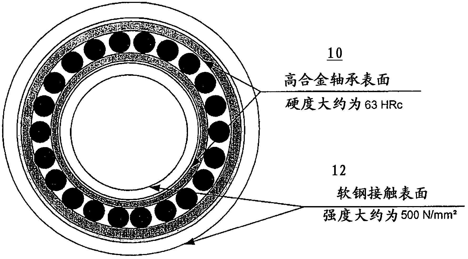
[0031] figure 1 A top plan view of a composite steel roller bearing according to the invention is shown. As described in detail herein, the roller bearing includes a high alloy bearing portion 10 and a mild steel bearing portion 12 .

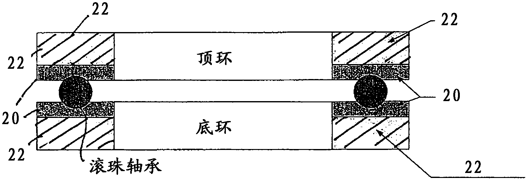
[0032] figure 2 A side view of a cross section taken through a ring bearing according to the invention is depicted. similar to figure 1 In the illustrated embodiment, the bearing includes a high alloy layer 20 and a mild steel layer 22 . Such annular bearings may be particularly suitable for use as azimuth bearings for wind turbines.

[0033] Such annular composite steel bearings are well suited for transmitting high axial forces and large bending moments with small relative movements between cooperating bearing components. Wind power installations may include such bearings between the head of a machine supported by its tower and the head of the tower, such as in Figure 15-Figure 16 in the public.

[0034] Bearings of the present invent...


PUM


Abstract

A bearing comprising: layers of high-strength steel and a base layer of mild steel fused together via a fusion zone; raceways machined across the bearing and having a higher strength than can be achieved using conventional steel hardening processes A much greater bearing support depth is obtained; and a retaining structure machined into at least the base layer of mild steel and used to retain the bearing on the underlying bearing support.

Description

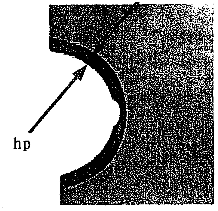
technical field [0001] The present disclosure relates to composite steel bearings. More specifically, the present disclosure relates to composite steel bearings and manufacturing processes and applications, including but not limited to wind turbines and other heavy equipment. Multiple ring bearings and flat bearings can be manufactured using aspects of the invention. Background technique [0002] Due to well-known metallurgical and chemical properties, the thickness of the hardened layer, especially when surface hardening is used, is strictly limited. As a result, bearing engineers are often limited by the depth of the case for a given load and / or environment. For example, Figures 3a, 4a and 5a show a number of different cross-sectional views taken through a steel bearing raceway, where the hardness pattern is designated "hp". The depth of hardened steel is limited, especially for induction hardened raceways. [0003] Prior to this invention, for large bearings, the need...

Claims


Application Information

Patent Timeline
Patent Type & Authority Applications(China)
IPC IPC(8): F16C33/60F16C33/64
CPCF16C33/64F16C2300/14F16C33/60F16C19/381Y02B10/30F16C2360/31
Inventor 约亨·科茨
Owner 约亨科茨
Learn More