Vibrating Belt Magnetic Separator

A vibrating belt and magnetic separator technology, which is applied in the fields of magnetic separation, solid separation, chemical instruments and methods, etc., can solve the problems that the bottom material cannot be magnetically separated, the material cannot be turned over, and the material cannot be evenly distributed, etc. The effect of improving mineral recovery rate and grade, high reliability of equipment operation, and reducing the number of process equipment

Inactive Publication Date: 2011-12-28
CHENGDU LEEJUN IND
View PDF10 Cites 23 Cited by
  • Summary
  • Abstract
  • Description
  • Claims
  • Application Information

AI Technical Summary

Problems solved by technology

[0009] The application number is 201010272770.3, the application date is August 31, 2010, the publication number is CN101972700A, and the name is a Chinese invention patent application for a vibrating fluidized bed dry magnetic separator. Horizontal layout is not convenient for material movement, and it is not suitable for magnetic separation of materials with a large amount of processing (such as after rolling); and because the magnetic force of the magnetic system is constant in the length direction of the vibrating plate, it cannot form a cyclic turnover of materials, and the same effect on the bottom layer The material cannot be magnetically separated; and there is no dust suction device, which cannot absorb the non-magnetic dust wrapped on the magnetic material, so that these materials cannot be sorted out, so it is not suitable for magnetic separation of materi

Method used


Image

  • Vibrating Belt Magnetic Separator
  • Vibrating Belt Magnetic Separator
  • Vibrating Belt Magnetic Separator

Examples


Embodiment Construction

[0036] Below in conjunction with accompanying drawing, the present invention is described in detail.

[0037] In order to make the object, technical solution and advantages of the present invention clearer, the present invention will be further described in detail below in conjunction with the accompanying drawings and embodiments. It should be understood that the specific embodiments described here are only used to explain the present invention, not to limit the present invention.

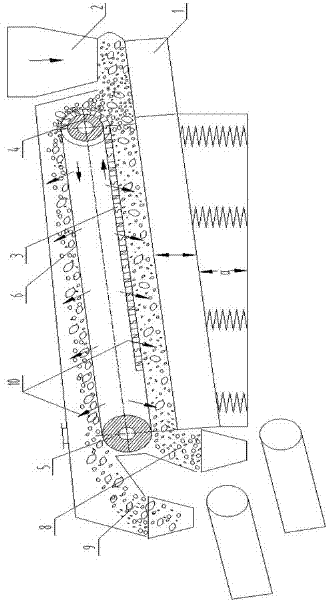
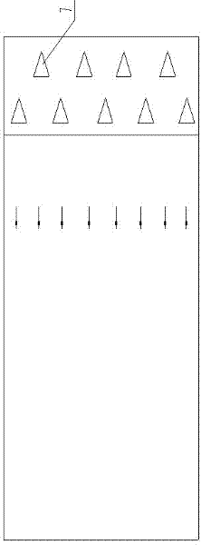
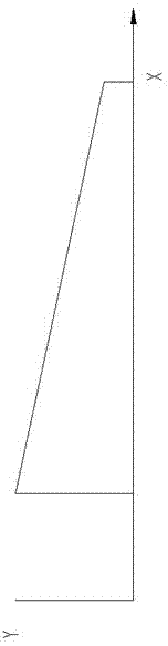
[0038] Such as figure 1 , figure 2 with image 3 As shown, the vibrating belt type magnetic separator of the present invention includes a conveyor belt 6 and a feed pipe 2, and a vibrating table 1 is arranged below the conveyor belt 6, so that the materials are subjected to vibration inertial force, which is convenient for magnetic materials and non-magnetic materials The feed pipe 2 is located above one end of the vibrating table 1, and the inner side of the conveyor belt 6 is provided with a...


PUM


Abstract

The invention discloses a vibrating belt type magnetic separator, which belongs to the field of dry magnetic separation equipment. The vibrating belt magnetic separator of the present invention includes a conveyor belt (6) and a feeding pipe (2), a vibrating platform is arranged under the conveyor belt (6), and the feeding pipe (2) is located on the side of the vibrating platform Above one end, a magnetic system (3) is arranged on the inner side of the conveyor belt (6). The vibrating belt magnetic separator of the present invention has simple structure, high efficiency and energy saving, low manufacturing cost, low use cost, high equipment operation reliability, and low maintenance cost; it can conveniently control the grade of concentrate, and is not only suitable for the selection of rich ore, but also It is suitable for the selection of lean ore and extremely lean ore, and can maximize the use of mineral resources; it can continuously process a large amount of magnetic materials after being rolled by a high-pressure roller mill, reduce the number of subsequent process equipment, and reduce the energy consumption of the process system. Improve the recovery rate and grade of minerals, which is conducive to popularization and application.

Description

technical field [0001] The invention relates to a dry-process magnetic separation equipment, in particular to a magnetic separator used for the separation of magnetic materials such as metal ores. Background technique [0002] With the gradual reduction of mines that can be mined in China, the grade of minerals has gradually decreased, and improving the recovery rate and grade of minerals has become an urgent problem for manufacturers to solve. With the development of grinding technology in recent years, the high-pressure roller mill based on the principle of material bed grinding has been widely used in the field of ore grinding, and has achieved obvious effects of increasing production and saving energy. However, due to the large material handling capacity of the high-pressure roller mill, there is currently a lack of matching dry magnetic separation equipment, and a large number of traditional methods are still used in the separation process. Mineral resources cannot be ...

Claims


Application Information

Patent Timeline
IPC IPC(8): B03C1/22
Inventor 何亚民魏勇徐智平
Owner CHENGDU LEEJUN IND
Why Eureka
Try Eureka