
Method for active strip breaking and continuous casting keeping of strip continuous casting

An active, thin-strip technology, applied in the field of continuous casting, can solve problems such as unstable casting process, unsuitable thin-strip continuous casting process, and unfavorable casting belt transportation, etc., to improve casting stability and efficiency, and the method of breaking the belt is simple Feasible, the effect of improving equipment utilization

Active Publication Date: 2013-06-19
BAOSHAN IRON & STEEL CO LTD
View PDF5 Cites 0 Cited by
  • Summary
  • Abstract
  • Description
  • Claims
  • Application Information

AI Technical Summary

Problems solved by technology

[0006] Comparing the above two strip breaking methods, the former mostly needs to be sheared before the cast strip is sent to the coiler, and the conventional strip steel coiling treatment method is used. This method is not suitable for the thin strip continuous casting process. Inapplicability, because if the quality of the belt head is poor, it is likely that the casting belt will be stuck on the conveyor roller table for other reasons before it is sent to the flying shear during long-distance transportation.
[0007] The latter method needs to strictly control the casting process parameters that cause the casting strip to break. During the strip breaking process, changing the corresponding parameters will lead to sharp fluctuations in the molten pool liquid level or fluctuations in the casting roll gap. These short-term fluctuations will lead to The casting process is unstable, and there is a risk of damaging the quality of the casting roll surface and the side sealing plate, which will lead to serious steel breakout accidents
Moreover, it is difficult to control the head of the cast strip with good quality by using this method, which is not conducive to the conveying of the cast strip

Method used


Image

  • Method for active strip breaking and continuous casting keeping of strip continuous casting
  • Method for active strip breaking and continuous casting keeping of strip continuous casting
  • Method for active strip breaking and continuous casting keeping of strip continuous casting

Examples


Embodiment Construction

[0046] The technical solution of the present invention will be further described in detail through two examples below.

[0047] Working condition 1. The casting machine actively breaks the belt to remove the head of the poor quality casting belt and cast continuously

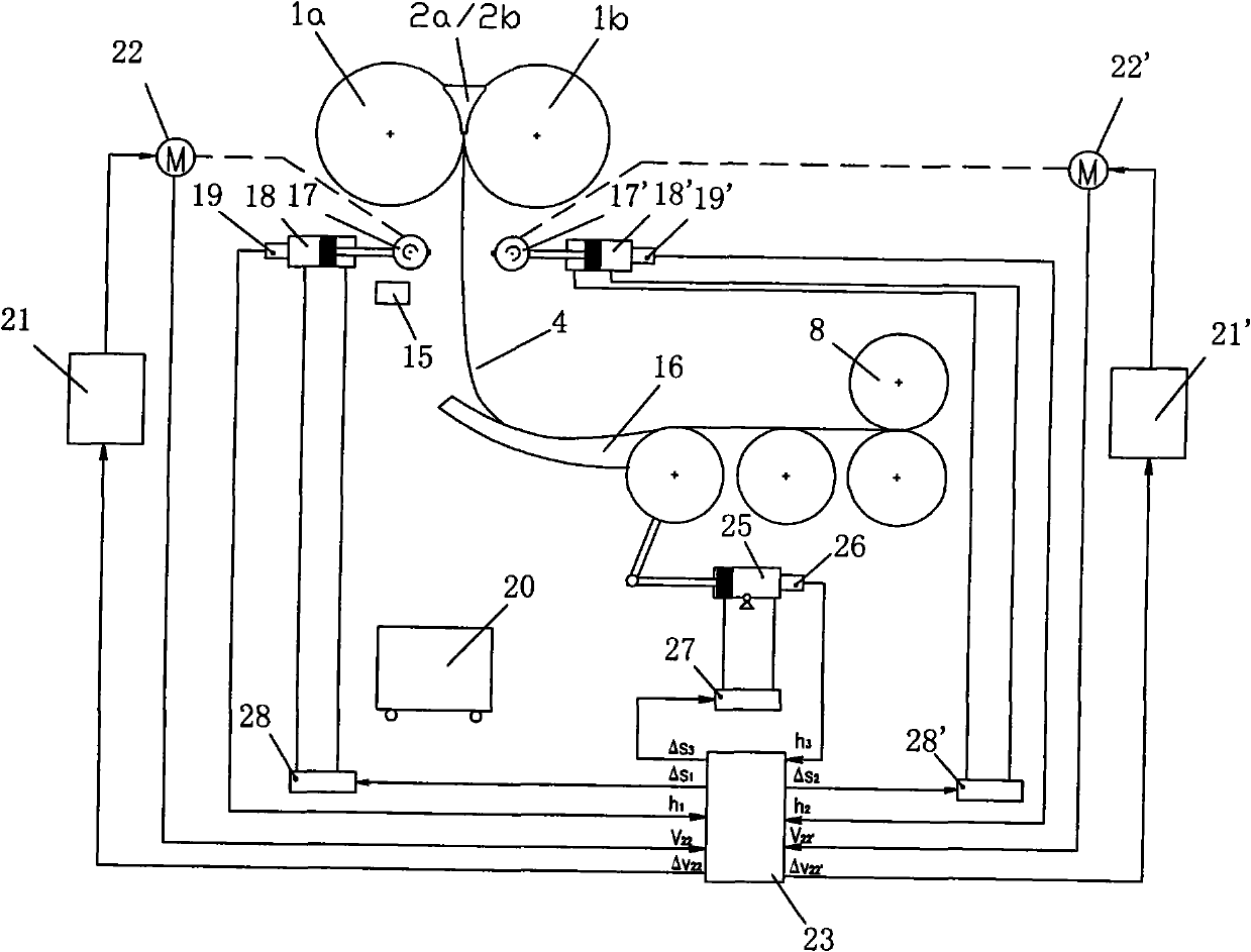
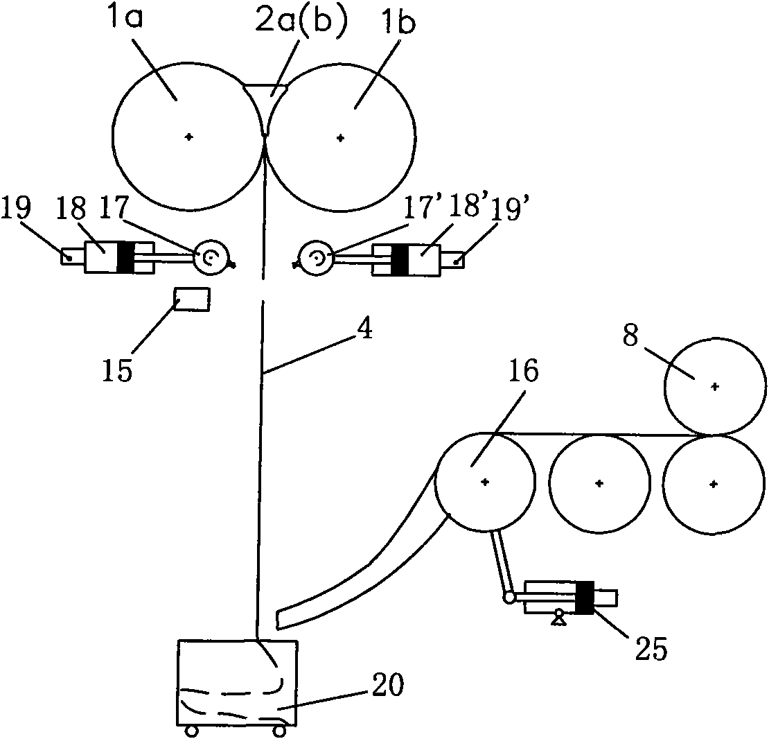
[0048] see Figure 2 ~ Figure 6 , enter the casting mode, and the broken strip detection device 15 installed under the thin strip continuous casting rolls monitors the continuous condition of the cast strip in real time, and sends the detection data to the strip steel guide control module 23. At this time, the swing guide plate 16 is at its lower limit. Its position is measured by a displacement sensor 26 located at the rear of its driving hydraulic cylinder 25 and controlled by a servo valve 27.

[0049] After the continuous length of the casting belt exceeds 10m, the hydraulic cylinders 18, 18' push the left and right gas injection devices 17, 17' to move towards the casting belt under the action of the servo...


PUM


Abstract

A method for active strip breaking and continuous casting keeping of strip continuous casting comprises the following steps of: two sets of active strip breaking devices, a set of cast strip breakage detection system and a set of strip steel guiding device are symmetrically arranged on the left and the right with a vertical cast strip as a centre under a strip continuous casting roll; in the strip continuous casting process, when the head portion of the cast strip is poor in quality at the initial stage of casting, breaking the head portion of the cast strip by the active strip breaking devices in an active manner, thereby removing the poor cast strip head portion; and when a coil of cast strip is curled completely and a curling machine needs to switch a reel, breaking the cast strip by the active strip breaking devices in the active manner at the outlet of a casting machine, and then matching the cast strip breakage detection system with the strip steel guiding device so that the subsequent cast strip can be continuous curled. The method is capable of removing head portion of the strip continuous casting cast strip having quality defects, and also capable of performing active separation and strip breakage while switching the reels of the curling machine; and the method is further capable of keeping casting operation continuity after the active strip breakage, thereby achieving the purpose of stable production and improving the casting success rate.

Description

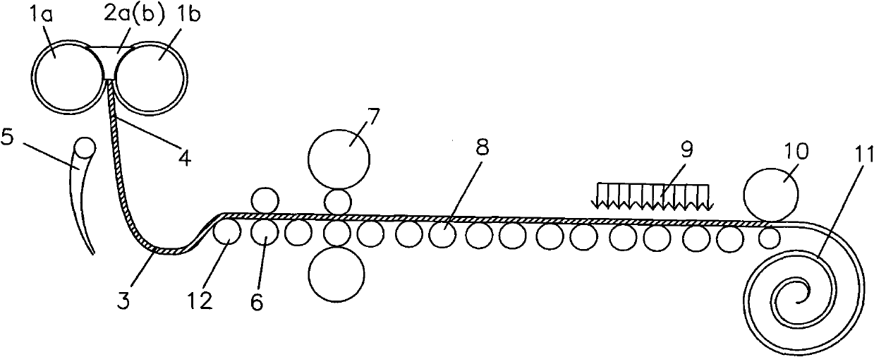
technical field [0001] The invention relates to continuous casting technology, in particular to a thin strip continuous casting method for actively breaking the strip and maintaining continuous casting. Background technique [0002] Twin-roll strip continuous casting technology is an advanced short-flow metallurgical process. Typical examples are figure 1 As shown, the molten steel is directly poured into a molten pool surrounded by two relatively rotating and rapidly cooling casting rolls 1a, 1b and side sealing plates 2a, 2b, and the molten steel is cooled on the rotating peripheral surface of the casting rolls and solidification, and then form a solidified shell and gradually grow, and then be squeezed together at the smallest gap between the two crystallization rollers 1a, 1b to form a strip 4, and the strip is guided to the looper guide roller 12 and the pinch roller 6 via the guide plate 5 , and form a looper 3 between the looper guide roll 12 and the casting rolls 1...

Claims


Application Information

Patent Timeline
Patent Type & Authority Patents(China)
IPC IPC(8): B22D11/06B22D11/126B22D11/16
Inventor 叶长宏顾龙发
Owner BAOSHAN IRON & STEEL CO LTD
Learn More