A flat glass chamfering machine

A flat glass and chamfering machine technology, which is applied to machine tools, grinders, and metal processing equipment suitable for grinding workpiece edges, and can solve problems such as complex connection control programs, large machine footprints, and low utilization of grinding wheels , to achieve the effect of simplifying machine configuration and control mode, reducing floor space and compact structure

Inactive Publication Date: 2011-12-28
GUANGDONG IVACO GLASS TECH
View PDF5 Cites 3 Cited by
  • Summary
  • Abstract
  • Description
  • Claims
  • Application Information

AI Technical Summary

Problems solved by technology

[0002] The machines currently used for chamfering glass edges usually use traditional grinding heads. Most of the traditional grinding heads use fixed structures. When there are errors in the shape and position of the glass, the glass cannot be processed, and some kinematic mechanisms are used to correct these errors. Compensation, but the cost is high and the control is complicated; the traditional machine is generally equipped with two grinding heads, usually one grinding head needs to grind three edges of the glass, and the processing speed is low; the two grinding heads are connected in a vertical On the straight guide rail or column, the two vertical sides of the glass are processed. Since the processing requires the glass to be in a stopped state, when the machine is used for in-line work, the front and rear of the machine need to be equipped with feeding and discharging sections to match the front and rear sections of the machine, which increases the To solve the problem of feeding, discharging and transition section, the machine occupies a large area, and the connection control program is complicated; the traditional machine processes the edge of the glass through the V-shaped grinding wheel installed on the two grinding heads, generally using V-shaped Grinding the grinding wheel, it is often necessary to dress the grinding wheel, the utilization rate of the grinding wheel is low, and the service life is short

Method used


Image

  • A flat glass chamfering machine
  • A flat glass chamfering machine
  • A flat glass chamfering machine

Examples


Embodiment approach 1

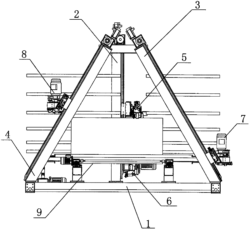
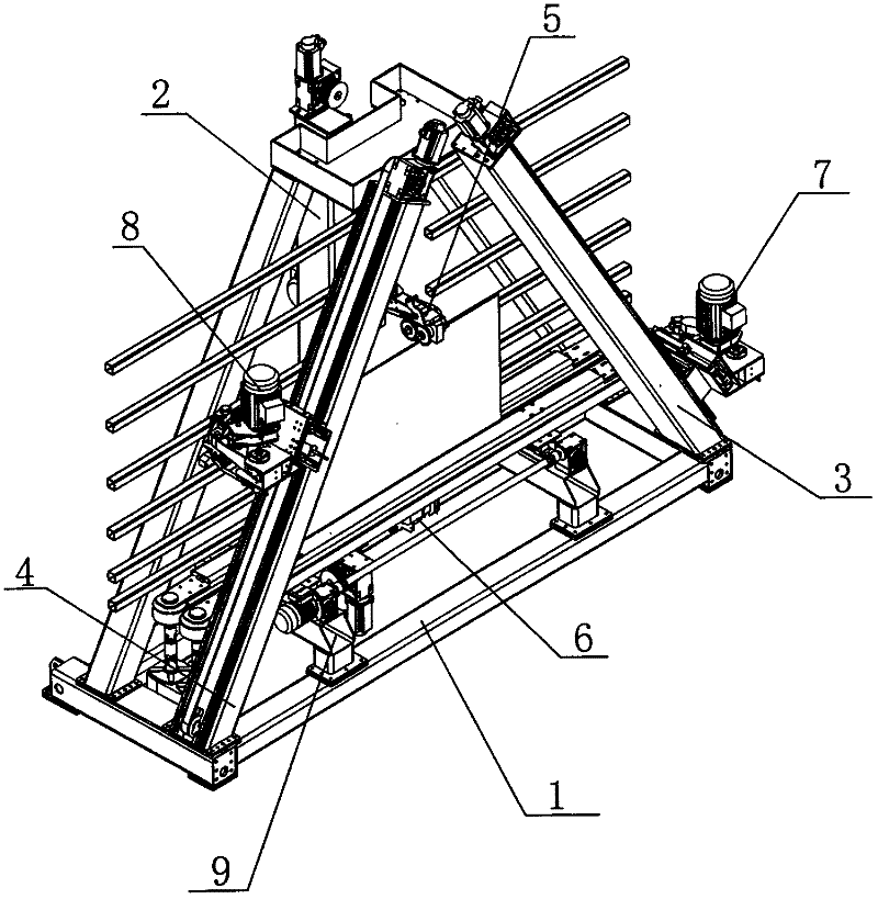
[0032] Such as Figure 1-11 As shown, a vertical plate glass chamfering machine includes a frame 1, a vertical guide rail 2, a right inclined guide rail 3, a left inclined guide rail 4, an upper edge grinding device 5, a lower edge grinding device 6, a right Along the grinding device 7, the left grinding device 8 and the clamp device 9, the clamp device 9 is arranged on the frame 1, the vertical guide rail 2 is arranged on the frame 1, and the right inclined guide rail 3 and the left inclined guide rail 4 are respectively It is obliquely arranged on the frame 1, and the upper edge grinding device 5 and the lower edge grinding device 6 are arranged on the vertical guide rail 2, and the right grinding device 7 is arranged on the right inclined guide rail 3, and the right grinding device 7 is arranged on the left inclined guide rail. 4 is provided with left grinding device 8.

[0033] The fixture device 9 includes a synchronous belt conveying type front chuck 91 and a rear chuck...

Embodiment approach 2

[0039] The technical solution of Embodiment 1 of the present invention can also be applied to the equivalent structural solution of a horizontal chamfering machine, wherein the frame 1 is a plane frame, and the vertical guide rail 2, the right inclined guide rail 3, and the left inclined guide rail 4 are all set on the same plane for positioning the flat glass in a horizontal conveying state, wherein the clamping device 9 is arranged on the frame 1, and the clamping device 9 can be set as a suction cup fixed structure to locate and transport the glass, and the vertical guide rail 2 is arranged on the horizontal guide rail. On the frame 1, the right inclined guide rail 3 and the left inclined guide rail 4 are arranged on the frame 1 obliquely with the horizontal guide rail respectively, and are correspondingly arranged horizontally, and the upper edge grinding device 5 and the vertical guide rail 2 are provided on the vertical guide rail 2 The lower edge grinding device 6 corres...

Embodiment approach 3

[0041] The technical scheme of Embodiment 1 of the present invention can also be applied to a backrest vertical plate glass chamfering machine with front and back symmetry, and its frame 1, vertical guide rail 2, right oblique guide rail 3, and left oblique guide rail 4 are arranged as corresponding backrests Symmetrical structure, the upper edge grinding device 5, the lower edge grinding device 6, the right edge grinding device 7, the left edge grinding device 8, and the fixture device 9 can be shared by the same linkage mechanism or independent mechanisms. Can achieve. Realize the technical effect of simplifying the production line and reducing the occupied area. When two sets of independent upper edge grinding device 5, lower edge grinding device 6, right edge grinding device 7, left edge grinding device 8, and clamping device 9 are respectively arranged in the front and back, the plate glass chamfering machine with two backrests Then realize the technical effect of indepe...


PUM


Abstract

The invention relates to a flat glass chamfering machine, comprising a rack, a vertical guide rail, a right oblique guide rail, a left oblique guide rail, an upper edge grinding device, a lower grinding device, a right edge grinding device, a right edge grinding device and a fixture device, wherein the fixture device is arranged on the rack; the vertical guide rail is arranged on the rack; the right oblique guide rail and the left oblique guide rail are respectively and slantwise arranged on the rack; the upper edge grinding device and the lower edge grinding device are arranged on the vertical guide rail; anda right grinding device is arranged on the right oblique guide rail while a left grinding device is arranged on the left oblique guide rail. The flat glass chamfering machine provided by the invention is applied to the industry of glass deep processing; chamfer processing is carried out on eight prisms of two surfaces of the flat glass, and grinding on an edge when glass moves is realized; and a mechanical device is adopted for compensating glass error; the flat glass chamfering machine is compact in structure and reasonable in layout; and the machine configuration and control mode of the machine are simplified, so that the cost thereof is reduced.

Description

technical field [0001] The present invention relates to a glass grinding machine, more specifically, to a processing machine for flat glass chamfering. Background technique [0002] The machines currently used for chamfering glass edges usually use traditional grinding heads. Most of the traditional grinding heads use fixed structures. When there are errors in the shape and position of the glass, the glass cannot be processed, and some kinematic mechanisms are used to correct these errors. Compensation, but the cost is high and the control is complicated; the traditional machine is generally equipped with two grinding heads, usually one grinding head needs to grind three edges of the glass, and the processing speed is low; the two grinding heads are connected in a vertical On the straight guide rail or column, the two vertical sides of the glass are processed. Since the processing requires the glass to be in a stopped state, when the machine is used for in-line work, the fro...

Claims


Application Information

Patent Timeline
Patent Type & Authority Applications(China)
IPC IPC(8): B24B9/10
Inventor 李富业
Owner GUANGDONG IVACO GLASS TECH
Why Eureka
Try Eureka