Anti-drawing and quick-break device at the glue inlet point of the mold

A technology of glue feeding and wire drawing prevention, applied in the field of plastic molds, can solve problems such as affecting product production efficiency, and achieve the effect of avoiding wire drawing.

Active Publication Date: 2011-12-28
思柏精密科技股份有限公司
View PDF5 Cites 4 Cited by
  • Summary
  • Abstract
  • Description
  • Claims
  • Application Information

AI Technical Summary

Problems solved by technology

The existing technology can only manually remove or control the injection temperature for this phenomenon. The former will obviously affect the production efficiency of the product, while the latter has certain limitations on the injection molding of the product.

Method used


Image

  • Anti-drawing and quick-break device at the glue inlet point of the mold
  • Anti-drawing and quick-break device at the glue inlet point of the mold
  • Anti-drawing and quick-break device at the glue inlet point of the mold

Examples


Embodiment 1

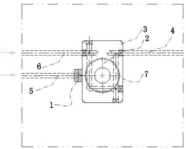
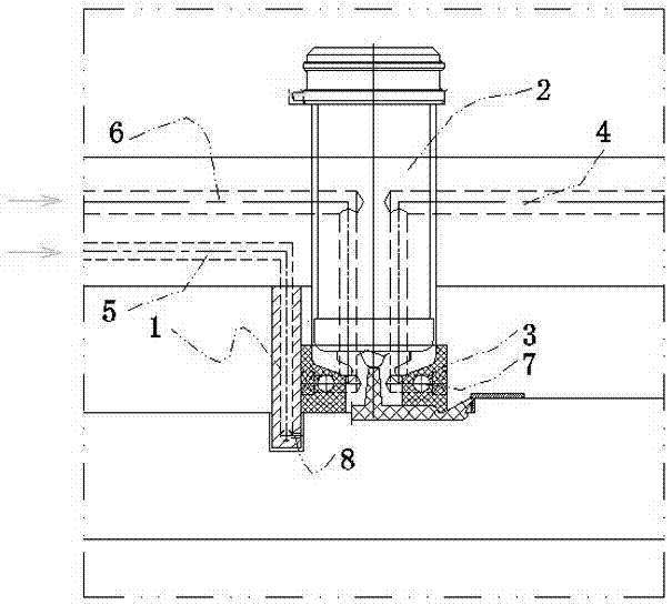
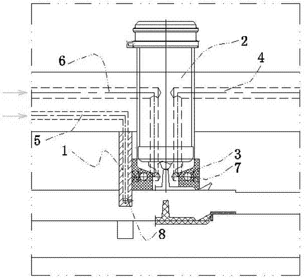
[0017] It includes a cooling insert 3 near the hot nozzle 2. The cooling insert 3 is provided with a water delivery pipe 7. One end of the water delivery pipe 7 communicates with the water inlet pipe 6 in the mould, and the other end communicates with the water outlet pipe in the mould. 4 communicated, and the water delivery pipe 7 is set near the outlet of the hot nozzle 2.

[0018] The cooling insert 3 is provided with a blowing block 1, or is connected with the blowing block 1, and one end of the blowing block 1 communicates with the air intake pipe 5 in the mould, and the blowing direction of the blowing hole 8 of the blowing block 1 It corresponds to the exit of hot nozzle 2, that is, the position of the gate of the product;

[0019] The blowing hole 8 of the blowing block 1 is below the cooling insert 3, the blowing direction of the blowing hole 8 is facing the gate part of the product after the mold is opened, and the bottom end surface of the cooling insert 3 is in con...


PUM


Abstract

The invention belongs to the technical field of plastic die, and especially relates to an anti-wiredrawing and quick-break-proof device for die dispensing points. The device provided by the invention comprises a cooling insert block 3 near a heat spout 2, wherein the cooling insert block 3 is provided with two anti-wiredrawing and quick-break-proof technical schemes: the first one is characterized in that the cooling insert block 3 is equipped with an air blowing block 1or is connected with the air blowing block 1, one end of which communicates with an air inlet pipe 5 inside the die, and theair blowing direction of a blow hole 8 is corresponding to an outlet of the heat spout 2; the second one is characterized in that a water conveying pipe 7 is disposed inside the cooling insert block 3, one end of the water conveying pipe 7 communicates with an inlet pipe 6 inside the die, the other end of the water conveying pipe 7 communicates with an outlet pipe 4 inside the die, and the water conveying pipe 7 is arranged near the outlet of the heat spout 2. The two technical schemes are preferably combined. According to the invention, cooling water flows inside the water conveying pipe to rapidly lower the temperature of the heat spout, and compressed air again blows air to cool a cast gate and breaks wire drawing in initial stage. Therefore, the wiredrawing phenomenon can be completely avoided by the dual functions.

Description

technical field [0001] The invention belongs to the technical field of plastic moulds, and relates to a solution to the wire drawing phenomenon caused by insufficient cooling at the gate during injection molding production, in particular to an anti-drawing quick-break device at the glue inlet point of the mold. Background technique [0002] In hot runner production, due to the high temperature near the hot nozzle, the hot nozzle cannot be cooled sufficiently. The rubber at the hot nozzle takes a long time to solidify. When the mold is opened, the rubber at the hot nozzle has not completely solidified, and the phenomenon of plastic stringing will occur. After the hot runner is pulled out of the cavity, there will be thin The glue thread is connected with the gate. If the glue sticks to the mold, it will damage the precision of the mold and the mold itself when the mold is closed; if it sticks to another batch of products, it will affect the appearance of the product, especi...

Claims


Application Information

Patent Timeline
Patent Type & Authority Applications(China)
IPC IPC(8): B29C45/73
Inventor 戚永幸陈有桦冯迎春
Owner 思柏精密科技股份有限公司
Why Eureka
Try Eureka