
Petroleum drill collar joint thread surface hot phosphating device

A thread surface phosphating device technology, applied in the field of oil drill collar joint thread surface thermal phosphating device, can solve problems such as unstable phosphating quality, affecting the service life of phosphating solution, pollution, etc., to reduce process operating costs and improve Drug utilization, simple and reliable operation

Inactive Publication Date: 2013-01-16
XI'AN PETROLEUM UNIVERSITY +1
View PDF3 Cites 0 Cited by
  • Summary
  • Abstract
  • Description
  • Claims
  • Application Information

AI Technical Summary

Problems solved by technology

[0003] At present, the phosphating devices on the threaded surface of domestic oil drill collar joints are relatively simple, and phosphating is mainly carried out by manually applying phosphating paste or dipping in an open hot phosphating tank. The quality of phosphating is unstable and the pollution is serious
The former has many uncertain factors in the phosphating treatment process, and the phosphating quality is difficult to control, while the latter thermal phosphating parts need to be frequently moved between the tanks, which consumes a lot of energy, and the structure of the thermal phosphating device is complex
At the same time, it is inconvenient to clean and maintain the various open tanks, especially the phosphating tank. The entry of any pollution source will directly cause the phosphating solution to age and affect the service life of the phosphating solution.
Furthermore, except for clear water, other functional liquids are corrosive to some extent and even contain toxic ingredients. Operators must wear masks, acid-proof gloves, protective glasses, water shoes, etc. to work, and the vaporized gas during heating is also harmful to the environment. cause damage

Method used


Image

  • Petroleum drill collar joint thread surface hot phosphating device
  • Petroleum drill collar joint thread surface hot phosphating device
  • Petroleum drill collar joint thread surface hot phosphating device

Examples


Embodiment Construction

[0024] The structural principle and working principle of the present invention will be described in detail below in conjunction with the accompanying drawings.

[0025] The present invention is based on the commonly used oil drill collar size specification NC50-70.

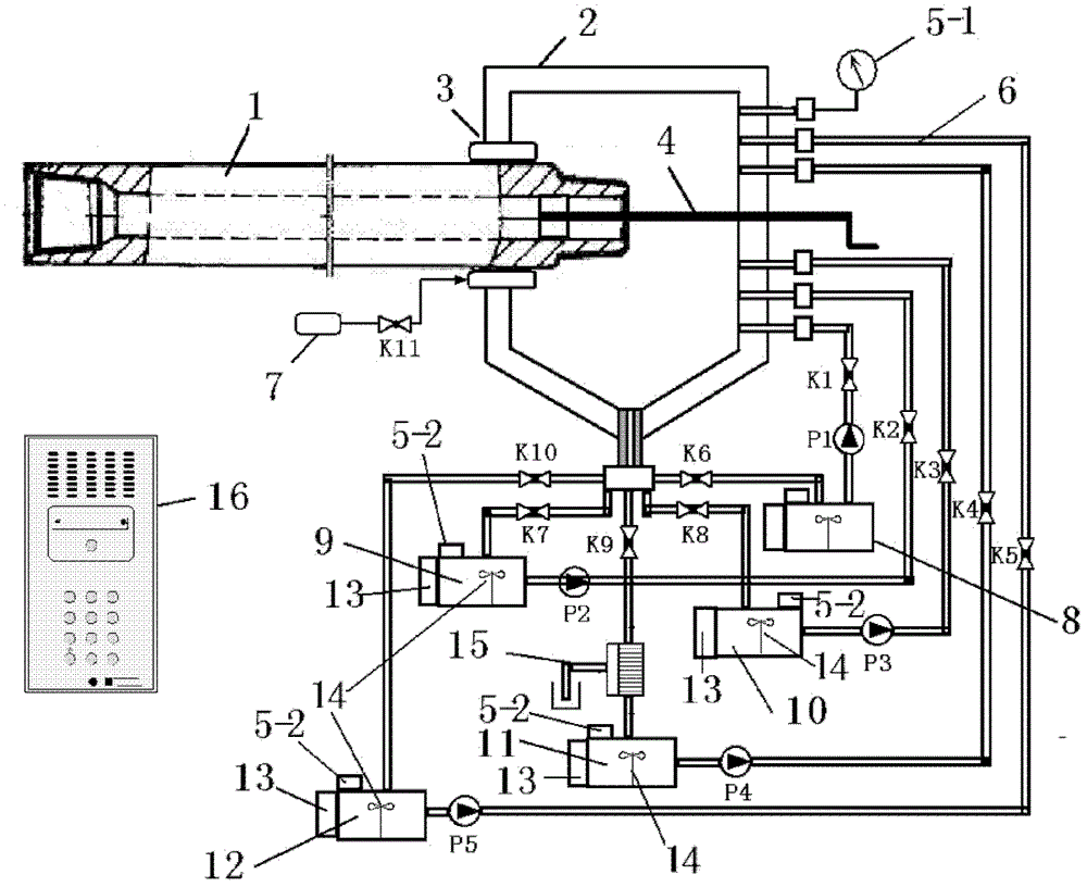
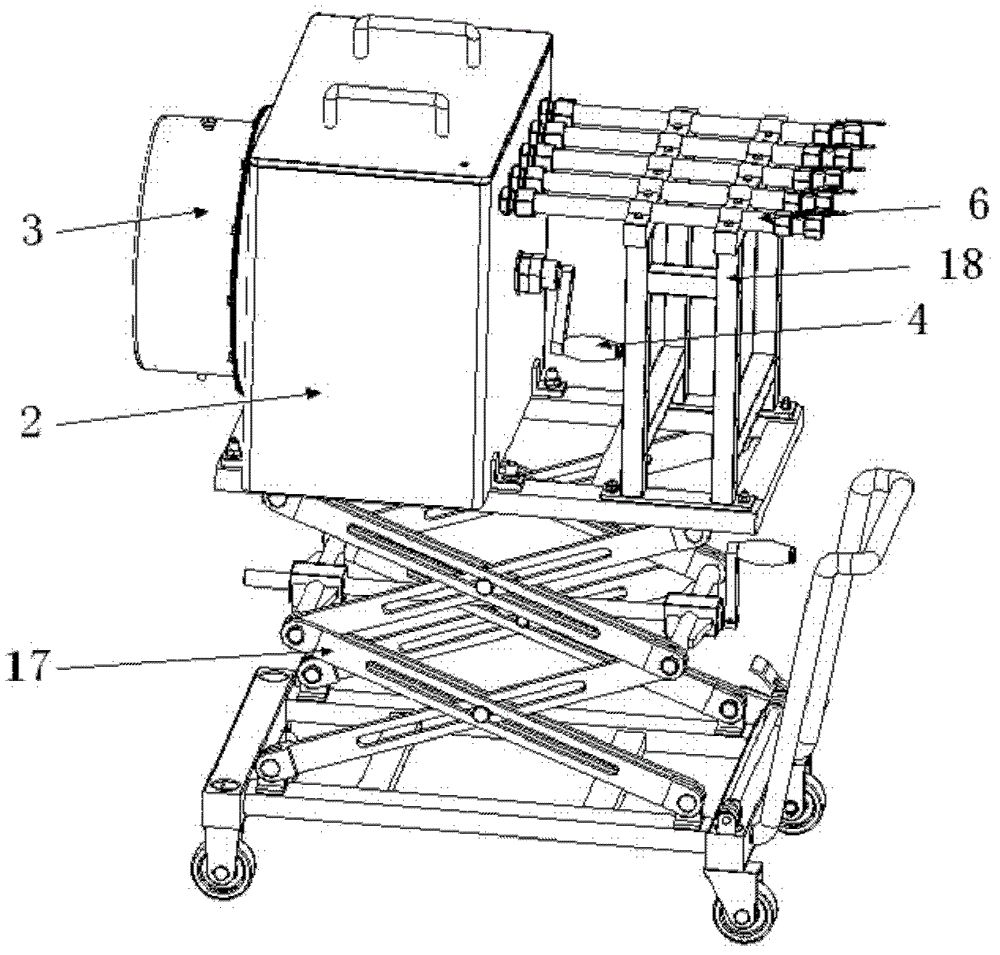
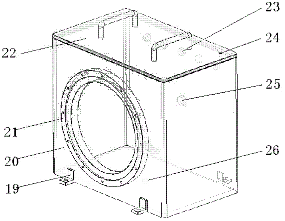
[0026] refer to figure 1 , figure 2 with image 3 , a thermal phosphating device for the threaded surface of a petroleum drill collar joint, comprising a phosphating tank bracket 17, the phosphating tank bracket 17 is connected to the phosphating tank assembly 2 with bolts through the phosphating tank connecting lug 19, and the phosphating tank assembly One side of 2 is connected with drill collar joint thread outer seal assembly 3 by bolts through outer seal box connection seat 21, and the other side of phosphating tank assembly 2 is connected with drill collar joint thread inner plug through inner plug assembly installation hole 25 The assembly 4 is connected, the five sets of manifolds 6 are connected to th...


PUM


Abstract

The invention relates to a petroleum drill collar joint thread surface hot phosphating device. The petroleum drill collar joint thread surface hot phosphating device comprises a phosphating pool assembly, wherein one side of the phosphating pool assembly is connected with a drill collar joint thread outer sealing assembly; the other side of the phosphating pool assembly is connected with a drill collar joint thread inner blocking assembly; five groups of manifolds are connected with five groups of loops; sensors, heaters, stirrers, electromagnetic valves and pumps in the five groups of loops are connected to a programmable logic controller (PLC); a drill collar joint is placed in a phosphating pool; and the technological treatment process of derusting, water washing, phosphating, passivation, drying and the like are implemented by the five groups of loops. The petroleum drill collar joint thread surface hot phosphating device has the characteristics of full sealability, low energy consumption, compact structure, simpleness in operation, automatic control and high phosphating efficiency.

Description

technical field [0001] The invention relates to the technical field of metal protection and surface treatment, in particular to a thermal phosphating device for threaded surfaces of oil drill collar joints. technical background [0002] The drill collars used in oil drilling are interconnected with threaded joints or connected with other drilling strings. These joints are not only subjected to normal loads such as tensile pressure, bending torque, vibration and shock, but also bear downhole fluids (such as oil, drilling, etc.) liquid, etc.) and corrosive media (such as H 2 S, CO 2 etc.), this harsh working condition puts forward higher requirements on the life, wear resistance, corrosion resistance and other properties of the connecting thread. Phosphating treatment can improve the corrosion resistance and other properties of the metal surface. The phosphating-treated oil drill pipe, tubing and other drilling tool joint threads have obvious improvements in wear resistance...

Claims


Application Information

Patent Timeline
Patent Type & Authority Patents(China)
IPC IPC(8): C23C22/07
Inventor 彭勇段正勇张利民闫文辉
Owner XI'AN PETROLEUM UNIVERSITY
Learn More