
Earth and rockfill dam body seepage monitoring structure provided with abandoned dreg site behind dam and construction method thereof

A construction method and technology for earth-rock dams, which are used in liquid/fluid solid measurement, dams, barrages, etc., can solve the problems of low accuracy, hidden dangers of dam operation safety, and inability to accurately measure the seepage flow of earth-rock dams. Guarantee the effect of safe operation

Active Publication Date: 2013-06-12
POWERCHINA HUADONG ENG COPORATION LTD
View PDF4 Cites 0 Cited by
  • Summary
  • Abstract
  • Description
  • Claims
  • Application Information

AI Technical Summary

Problems solved by technology

[0003] This layout method has the following problems: First, it is impossible to accurately measure the seepage of the earth-rockfill dam body, and the accuracy of the calculation value based on the readings of the piezometer is not high; The drainage effect of the dam will also be reduced, and there are certain safety hazards in the operation of the dam.

Method used


Image

  • Earth and rockfill dam body seepage monitoring structure provided with abandoned dreg site behind dam and construction method thereof
  • Earth and rockfill dam body seepage monitoring structure provided with abandoned dreg site behind dam and construction method thereof
  • Earth and rockfill dam body seepage monitoring structure provided with abandoned dreg site behind dam and construction method thereof

Examples


Embodiment Construction

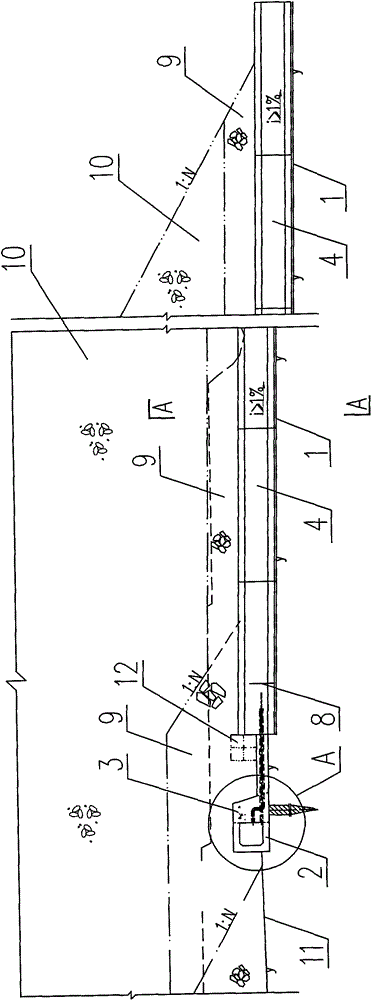
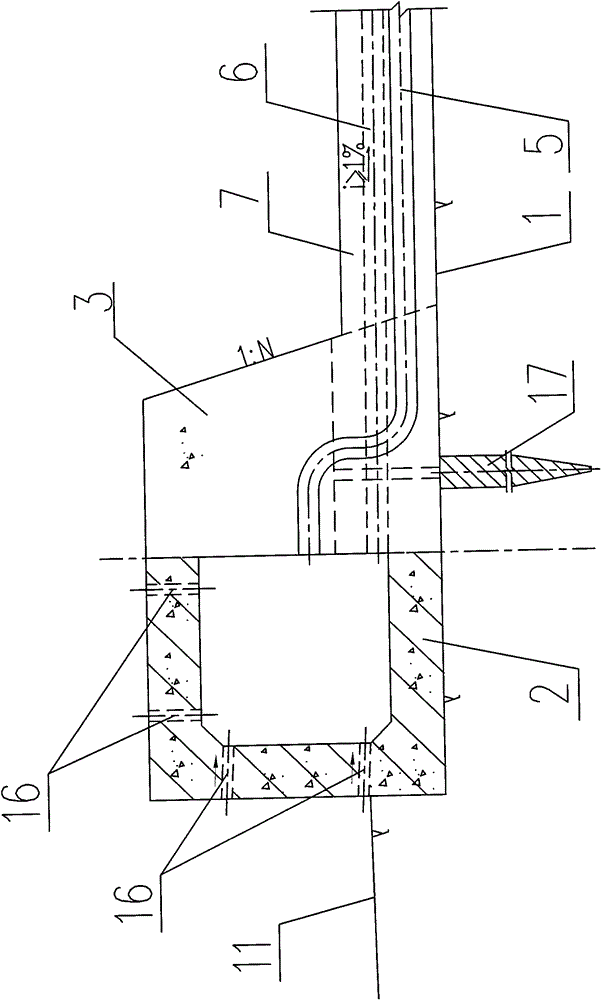
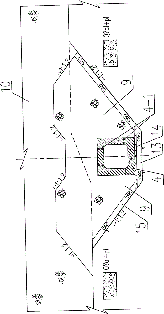
[0027] like Figure 1-Figure 3 As shown, the present embodiment includes a spoil ground 10 and a permeable rockfill area 9 located below the spoil ground, and a concrete retaining wall 3 is poured into the permeable rockfill area 9 at the lowest point of the riverbed at the foot of the downstream dam body of the earth-rock dam. , in this example, the height of retaining wall 3 is 3m, the thickness is 1-2m, and is arranged perpendicular to the direction of water flow; The upstream side of described retaining wall 3 pours the reinforced concrete water collection box culvert 2 that is connected with it, and is also perpendicular to Arrangement in the direction of water flow, several through holes are reserved on the top plate of the culvert 2 of the water collection box and the upstream side plate, and a PVC water collection pipe 16 with a diameter of 10mm is buried (the head is covered with geotextile protection) to centrally collect the seepage water of the dam foundation to the...


PUM


Abstract

The invention relates to an earth and rockfill dam body seepage monitoring structure provided with an abandoned dreg site behind a dam and a construction method thereof. The technical problem to be solved by the invention is to provide an earth and rockfill dam body seepage monitoring structure provided with an abandoned dreg site behind a dam and a construction method thereof, which can be used for effectively and accurately measuring the seepage discharge of the dam and ensuring permanent smooth drainage of the abandoned dreg site behind the dam. The technical scheme for solving the problemis that: the earth and rockfill dam body seepage monitoring structure provided with the abandoned dreg site behind the dam comprises an abandoned dreg site and a permeable rockfill area which is positioned below the abandoned dreg site; concrete retaining walls are poured at the downstream dam toe of a dam body and in the permeable rockfill area; a water collecting box culvert vertical to the water flow direction is poured on the upstream side of each retaining wall; a concrete longitudinal drainage box culvert is embedded along the full length of the permeable rockfill area on a downstream side; a drain pipe and a mud pipe which are communicated with the water collecting box culvert and the drainage box culvert are embedded into each retaining wall; a plurality of through holes are formed on a top plate and an upstream side plate of the water collecting box culvert; a water collecting pipe is embedded; and a measuring weir is arranged in the drainage box culvert. The earth and rockfill dam body seepage monitoring structure is mainly applied to an earth and rockfill dam provided with the abandoned dreg site behind the dam.

Description

technical field [0001] The invention relates to an earth-rock dam body seepage monitoring structure and a construction method for an earth-rock dam with a spoil ground behind the dam, and is mainly suitable for an earth-rock dam with a spoil ground behind the dam. Background technique [0002] In hydropower and water conservancy projects, especially in pumped storage power stations, in order to save project land, the layout type of spoil ground is often adopted behind the earth-rock dam. In order to ensure the smooth discharge of water seepage from the dam body and the mountains on both sides, a certain thickness of permeable rockfill material is usually paved at the bottom of the spoil yard, and a piezometric tube is buried at the foot of the downstream dam. flow. [0003] This layout method has the following problems: First, it is impossible to accurately measure the seepage of the earth-rockfill dam body, and the accuracy of the calculation value based on the readings of...

Claims


Application Information

Patent Timeline
Patent Type & Authority Patents(China)
IPC IPC(8): E02B7/06E02B8/00G01F1/00
Inventor 王樱畯黄维赵琳吴关叶
Owner POWERCHINA HUADONG ENG COPORATION LTD
Learn More