
A wire rope anti-twist connection device

A connecting device and wire rope technology, applied in the direction of transmission elements or pulley ropes or cables, textile cables, belts/chains/gears, etc., to achieve simple and fast connection and fixation, and improve the service life

Inactive Publication Date: 2011-12-28
TAIYUAN UNIV OF TECH
View PDF6 Cites 10 Cited by
  • Summary
  • Abstract
  • Description
  • Claims
  • Application Information

AI Technical Summary

Problems solved by technology

This will not only cause trouble in the process of changing the rope, such as when the joint of the two ropes passes through the sky wheel, but also cause the new rope to wear and tear in the future due to the existence of torsion, which will affect the service life.

Method used


Image

  • A wire rope anti-twist connection device
  • A wire rope anti-twist connection device
  • A wire rope anti-twist connection device

Examples


Embodiment Construction

[0016] Below in conjunction with accompanying drawing and specific example, the specific embodiment of the present invention is described in further detail:

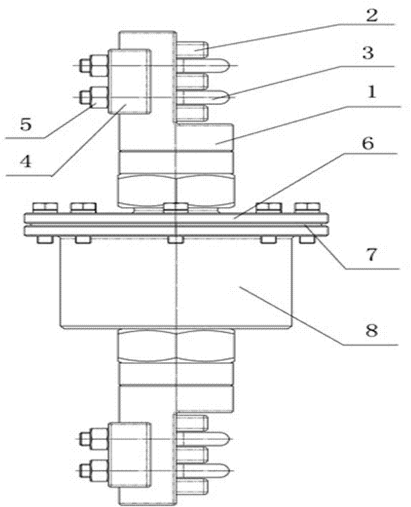
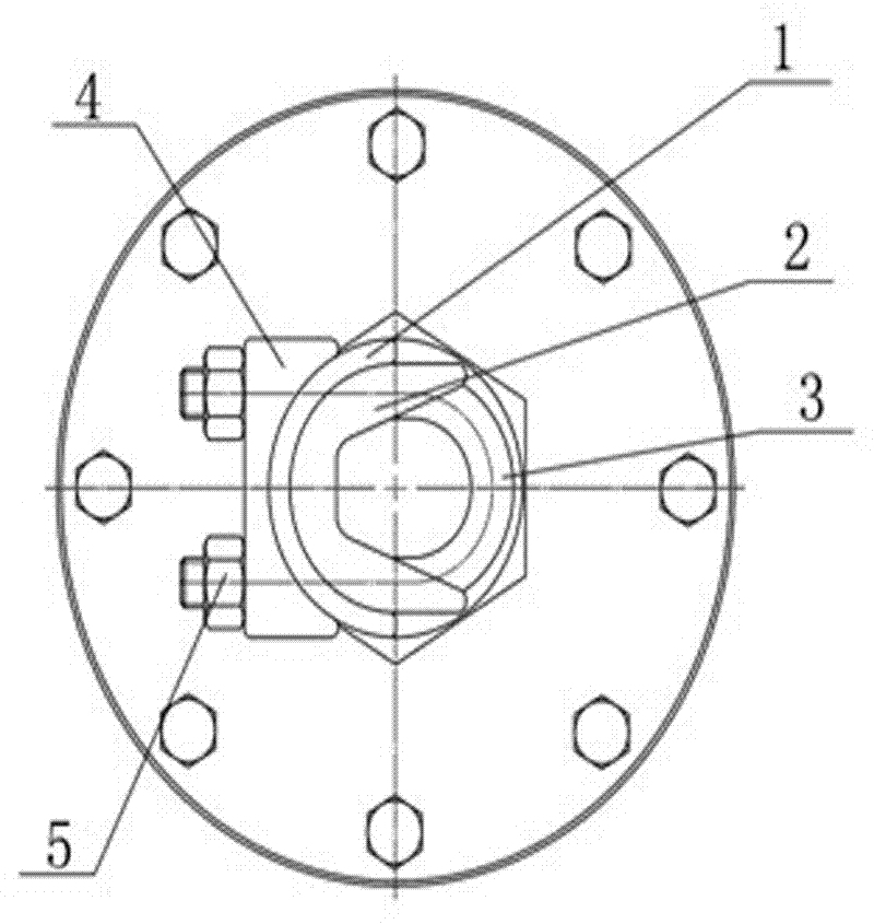
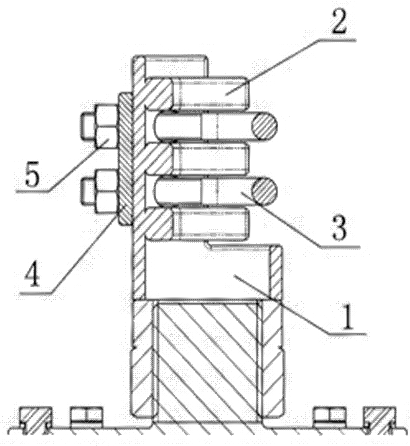
[0017] Such as Figure 1-4 As shown, a wire rope anti-twist connection device is implemented, which consists of two parts: a wire rope fixing device and a torsion release device. Among them, the wire rope fixing device is composed of threaded sleeve 1, trapezoidal groove 2, U-shaped card 3, pressure block 4, lock nut 5; the twist release device is composed of end cover 6, gasket 7, housing 8, rotating shaft 9, angle The contact bearing 10 and the thrust ball bearing 11 are constituted. Three trapezoidal grooves are evenly distributed and welded to the inner wall of one end of the threaded sleeve, and four through holes are drilled on the pipe wall between each trapezoidal groove, and the pressure blocks with the same four through holes are placed on the threaded sleeve correspondingly. On the outer wall of the pipe, th...


PUM


Abstract

The invention relates to an anti-torsion connection device of a steel wire rope, comprising steel wire rope fixing devices on both ends and a torsion release device in the middle; each steel wire rope fixing device comprises a threaded sleeve, a trapezoidal groove, a U-shaped clip, a pressure block and a locking nut; and the torsion release device comprises an end cover, a gasket, a shell body, arotating shaft and a bearing. The anti-torsion connection device is adopted for connecting steel wire ropes, so that unsafe hidden hazards caused by the steel wire ropes when passing through a head sheave and the like due to overturn, simultaneously the quick connection and fixation of an old rope and a new rope are realized through a clamping function between the trapezoidal groove and the U-shaped clip in the threaded sleeve, the new rope is prevented from more serious wear caused by torsion due to the torsion of the old rope through the free rotation of the bearing in the torsion release device, and the service life and the safety of the steel wire ropes are improved.

Description

technical field [0001] The invention relates to a steel wire rope connection device, in particular to a technical solution for a steel wire rope anti-twist fast connection device. [0002] Background technique [0003] Steel wire rope has high strength, light weight, stable operation, not easy to break suddenly, and reliable operation. It is widely used in material handling machinery and is a flexible structure with wide application. Under the action of tension, the helical elements in the wire rope interact to generate internal forces, which can be decomposed into axial components parallel to the axis of the wire rope and radial components perpendicular to the axis of the wire rope, and the radial component makes the rope At the same time, when the external conditions are unstable, such as changes in the load of the steel wire rope, the steel wire rope will also be subjected to torsion. Under the influence of such internal force or external factors, the steel wire rope wil...

Claims


Application Information

Patent Timeline
Patent Type & Authority Applications(China)
IPC IPC(8): F16G11/10
Inventor 寇子明高贵军李军霞卫进吴娟
Owner TAIYUAN UNIV OF TECH
Learn More