A central heating system with low temperature return water
A central heating and low-temperature technology, applied in hot water central heating systems, heating systems, household heating, etc., to achieve the effect of improving heating capacity and improving heat network delivery capacity
- Summary
- Abstract
- Description
- Claims
- Application Information
AI Technical Summary
Problems solved by technology
Method used
Image

Examples
Embodiment 1
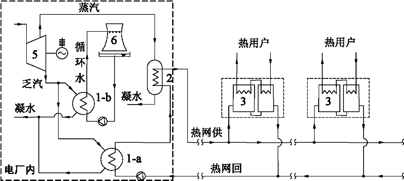
[0019] Embodiment 1: as figure 1 As shown, the exhaust steam of the steam turbine in the power plant adopts the water-cooling mode, the exhaust steam outlet of the steam turbine is connected with the condenser 1-b of the power generation system, and the steam extraction pipeline of the steam turbine is connected with the steam-water heat exchanger 2. Heat pump heat exchange units 3 (patent number: ZL200810101064.5) are installed in each thermal station, and the first condenser 1-a is installed in the power plant in parallel with the existing condenser 1-b of the power generation system of the power plant.
[0020] After the high-temperature primary network water supply is sent out of the power plant, it enters the above-mentioned heat pump heat exchange unit 3 to heat the secondary network hot water to supply heat users, and at the same time realize the cooling of the primary network hot water return water. After the low-temperature primary network return water returns to the p...
Embodiment 2
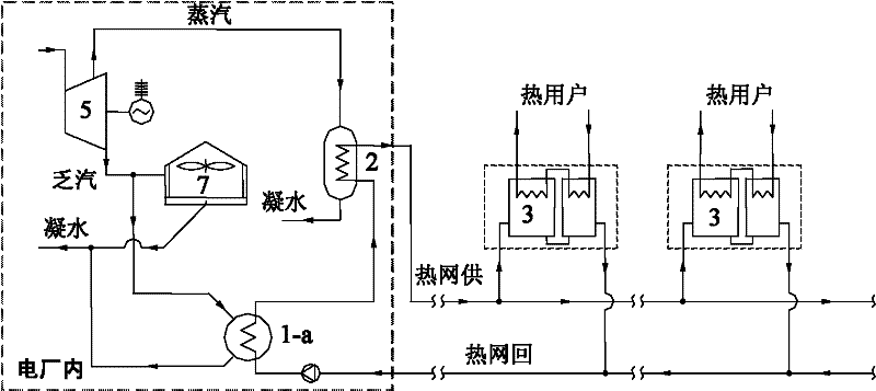
[0022] Embodiment 2: as figure 2 As shown, the exhaust steam of the steam turbine in the power plant adopts the air-cooling mode, and the exhaust steam outlet of the steam turbine is connected with the air-cooling island 7. The system of the present invention is equipped with a heat pump type heat exchange unit 3 in each thermal station of the heating network, and the first condensing unit 3 is installed in the power plant. The boiler 1-a is connected in parallel with the air cooling island 7 of the power plant. Compared with Embodiment 1, the exhaust steam of the steam turbine of the power plant in this embodiment adopts the air-cooling mode, and the others are the same as Embodiment 1.
[0023] When the exhaust heat of the steam turbine 5 cannot be fully recovered, the remaining exhaust steam can still be directly cooled in the air-cooling island 7 of the power plant. Therefore, it will not cause adverse effects on the original power generation system of the power plant.
Embodiment 3
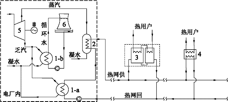
[0024] Embodiment 3: as image 3 As shown, heat pump heat exchange units 3 are partially installed in each thermal station of the heating network, and conventional water-water heat exchangers 4 are installed in the other part. The condensers 1-b of the power plant power generation system are connected in parallel. Compared with Example 1, the difference is that a conventional water-water heat exchanger 4 is partially installed in the heating network thermal station of this example, which cannot lower the temperature of the return water of the primary network to be lower than that of the secondary network. This part of the high-temperature primary network return water will be mixed with the low-temperature primary network return water cooled by the heat pump heat exchange unit 3 and then returned to the power plant for heating. The higher the temperature is, the lower the return water temperature of the primary network is, the more beneficial it is to recover the exhaust steam...
PUM
 Abstract
Description
Claims
Application Information
 - R&D
- Intellectual Property
- Life Sciences
- Materials
- Tech Scout
- Unparalleled Data Quality
- Higher Quality Content
- 60% Fewer Hallucinations
Browse by: Latest US Patents, China's latest patents, Technical Efficacy Thesaurus, Application Domain, Technology Topic, Popular Technical Reports.
© 2025 PatSnap. All rights reserved.Legal|Privacy policy|Modern Slavery Act Transparency Statement|Sitemap|About US| Contact US: help@patsnap.com