A method for detecting grounding faults of bridge cables

A technology of fault detection and cable grounding, applied in the direction of the fault location, etc., can solve the problems of the eccentric magnetic field requiring special equipment and personnel limitations, the environmental interference of the metallic ground fault audio method, and the difficulty of measuring the ground fault with the audio induction method, etc., to achieve The effect of saving measurement time, high safety, and portable test equipment

Active Publication Date: 2016-01-13
SHANGHAI BAOSTEEL IND TECHNOLOGICAL SERVICE
View PDF4 Cites 0 Cited by
  • Summary
  • Abstract
  • Description
  • Claims
  • Application Information

AI Technical Summary

Problems solved by technology

[0014] The advantages and disadvantages of the pulse current method are similar to the pulse voltage method
[0015] 2. Directly buried cable fault fixed point
[0021] In practical applications, when there are ferromagnets around the cable or at the cable joint, the received signal is often stronger, so it is difficult to measure the ground fault by using the audio induction method, and the fault point is often not found
[0022] 3. Fixed point of exposed cable fault
However, this method requires the inspector to directly contact the live cable, which is less safe.
[0036] Based on the above analysis, the current shortcomings in the detection of cable ground fault points mainly include: the use of the bridge method is affected by the resistance; the pulse method and the acoustic measurement method require high voltage, and sometimes the test time is long; The audio method has problems such as environmental interference; the local overheating method and the current detection method have problems such as electric shock and blindness; the eccentric magnetic field requires special equipment and personnel, and has large limitations.

Method used


Image

  • A method for detecting grounding faults of bridge cables
  • A method for detecting grounding faults of bridge cables
  • A method for detecting grounding faults of bridge cables

Examples


Embodiment 1

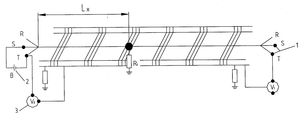
[0066] Embodiment 1: A ground fault occurs in the main insulation of the S phase of the raw power cable, and the specific parameters of the cable are: length L=750 meters, cross-sectional area S=50mm 2 , Ground resistance R f = 15 ohms.

[0067] Loop current output is 10 amps

[0068] The voltage is measured as follows: V 1 =1.531VV 2 =1.169V

[0069] Then L X =(V 2 / V 1 +V 2 )*L=(1.169 / 1.531+1.169)*750=324.7 meters

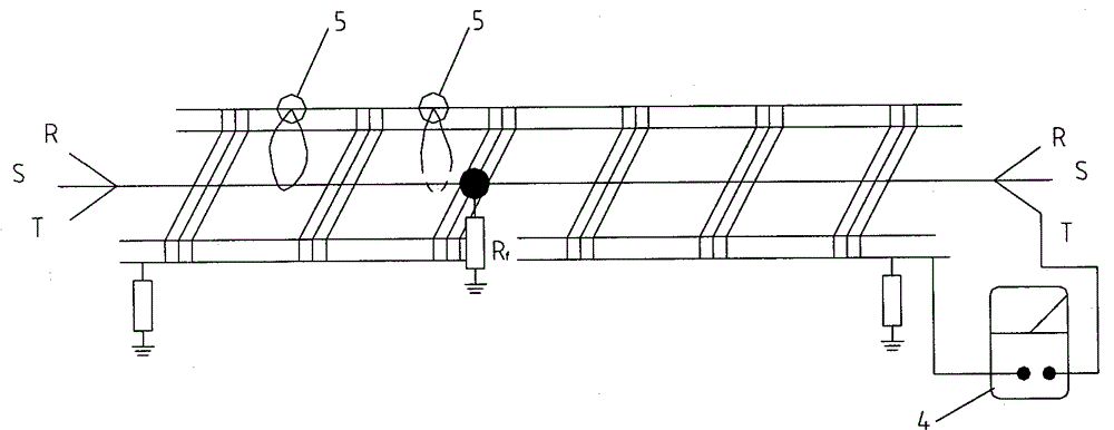
[0070] This measurement method is used for precise determination at a distance of 300 meters near the rough measurement distance. When the insulating rope moves to 320 meters, due to the influence of the insulation of the insulating rope itself, the grounding resistance R f Elimination, the resistance value of the multimeter resistance measurement gear connected to the fault loop immediately changed from 15Ω to infinity, and at this time it can be determined that the fault point is at 320 meters. All the work from the beginning of the measurement to the...

Embodiment 2

[0071] Embodiment 2: A ground fault occurs in the T-phase main insulation of the power cable, and the specific parameters of the cable are: length L=1300 meters, cross-sectional area S=185mm 2 , Ground resistance Rf = 0 ohms.

[0072] Loop current output is 10 amps

[0073] The voltage is measured as follows: V 1 =0.178VV 2 =1.087V

[0074] Then L X =(V 2 / V 1 +V 2 )*L=(1.087 / 0.178+1.087)*1300=1117.1 meters

[0075] The measurement method is used for precise determination at a rough measurement distance of 1100 meters. When the insulating rope 5 moves to 1120 meters, due to the influence of the insulation of the insulating rope itself, the grounding resistance R f Elimination, the resistance value of the multimeter resistance measurement gear connected to the fault circuit changed from 0Ω to infinity immediately, and at this time it can be determined that the fault point is at 1120 meters. Three people completed the whole work from measurement to fault location within...


PUM


Abstract

The invention relates to a detection method for a cable grounding fault. A method for detecting a grounding fault of a bridge cable, which includes: connecting one end of the faulty cable to the output end of a DC stabilized power supply, and the other end to be short-circuited to any other intact phase cable; connecting the output end of the DC stabilized power supply to the other At the other end of any one-phase cable; turn on the DC stabilized power supply to keep the output current stable at 5-10A; use a DC voltmeter to measure the values ​​V1 and V2 within the voltage range of the two ends of the faulty cable to the bridge frame; that is The rough location of the fault point of the cable can be calculated; then the DC stabilized power supply is released, and one end of the resistance gear of the multimeter is connected to one end of the faulty cable, and the other end is grounded; When the resistance value of the multimeter reaches the maximum value, that is, the position where the insulating rope moves is the fault point. The invention can be used for fast and accurate detection of the grounding fault point of the cable laying bridge.

Description

technical field [0001] The invention relates to electrician detection, in particular to a detection method for cable grounding faults. Background technique [0002] For a long time, many measurement methods and instruments have emerged for cable fault detection. These methods and instruments are suitable for different fault situations and have their own advantages and disadvantages. Domestic and foreign literature introduction and practical application are compared and evaluated as follows. [0003] 1. Cable fault location [0004] (1) Bridge method: This is a classic test method. Since the cable DC resistance is proportional to the length, the distance to the fault point can usually be calculated by measuring the proportional relationship between the cable fault point and the resistance value of the measurement end and end. [0005] The advantages of the bridge method are simplicity, convenience, and high accuracy. [0006] The disadvantage of the bridge method is that ...

Claims


Application Information

Patent Timeline
Patent Type & Authority Patents(China)
IPC IPC(8): G01R31/08
Inventor 戴静旭刘杰潘永明繆金龙范文国朱华龙陈长海
Owner SHANGHAI BAOSTEEL IND TECHNOLOGICAL SERVICE
Why Eureka
Try Eureka