Self-powered conditioning circuit for wireless sensors based on space electromagnetic energy

A wireless sensor and conditioning circuit technology, which is applied to electrical components, output power conversion devices, and irreversible AC power input to DC power output, etc. It can solve the problems of different circuit transmission efficiencies and different control signal duty ratios.

Inactive Publication Date: 2011-12-28
SHANDONG UNIV
View PDF5 Cites 4 Cited by
  • Summary
  • Abstract
  • Description
  • Claims
  • Application Information

AI Technical Summary

Problems solved by technology

The duty cycle of the control signal is different, the time for the current to flow is different, the loss of the diode and other devices is different, and the transmission efficiency of the circuit will also be different.

Method used


Image

  • Self-powered conditioning circuit for wireless sensors based on space electromagnetic energy
  • Self-powered conditioning circuit for wireless sensors based on space electromagnetic energy
  • Self-powered conditioning circuit for wireless sensors based on space electromagnetic energy

Examples


Embodiment 1

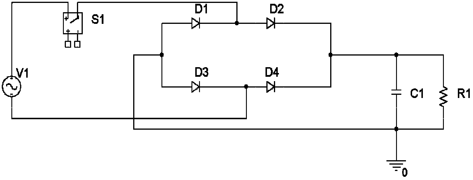
[0066] Embodiment 1: as Figure 7 As shown, the wireless sensor self-supply conditioning circuit based on space electromagnetic energy includes an external input power supply V3, the external input power supply V3 is connected to the AC input terminal of the rectified full bridge, and the DC output positive terminal and negative terminal of the rectified full bridge There are four branches connected in parallel, among the four branches, the first branch is a capacitor C2, and the capacitor C2 is connected in parallel with the second branch composed of the switching element M and the inductor L2 in series, and the diode D5 and the capacitor C3 The third branch formed in series is connected in parallel to both ends of the inductor L2 in the second branch, and the fourth branch formed by the load R3 is connected in parallel to both ends of the capacitor C3 in the third branch. The anode of the diode D5 in the third branch is connected in series with the capacitor C3. One end of ...

Embodiment 2

[0068] Embodiment 2: as Figure 9 As shown, the wireless sensor self-supply conditioning circuit based on space electromagnetic energy includes an external input power supply V4, and the output of the external input power supply V4 is connected in parallel with two T-shaped circuits, which are T-shaped circuit I and T-shaped circuit II, and the capacitor The parallel branch of C4 and load R4 is connected to the output terminals of the two T-shaped circuits. The T-shaped circuit I includes a branch circuit composed of an inductor L1 connected in series with the anode of a diode D1, and a high-frequency switch S1 is connected to the anode of the diode D1. The T-shaped circuit II includes a branch circuit composed of a high-frequency switch tube S2 connected in series with the anode of a diode D2, and an inductor L2 is connected to the anode of the diode D2. One end of the power supply is grounded.

[0069] Such as Figure 9 As shown, the technical solution does not contain th...


PUM


Abstract

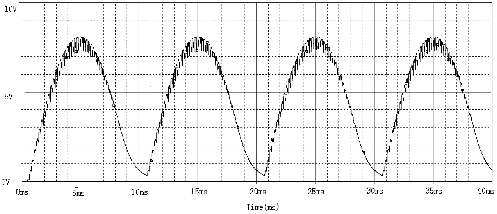
The invention discloses a wireless sensor self-supply conditioning circuit based on space electromagnetic energy, which includes an external input power supply connected to the AC input terminal of the rectified full bridge, and the DC output positive terminal and negative terminal of the rectified full bridge There are four branches connected in parallel, among the four branches, the first branch is a capacitor C2, and the capacitor C2 is connected in parallel with the second branch composed of the switching element M and the inductance L2 in series, and the diode D5 and the capacitor A third branch composed of C3 in series is connected in parallel to both ends of the inductor L2 in the second branch, and a fourth branch composed of load R3 is connected in parallel to both ends of the capacitor C3 in the third branch. The simulation results of this scheme show that the output voltage tends to be stable after 5 power frequency cycles, and the form factor is greatly improved. Using the algorithm in Section 3.1, it can be seen that the form factor is basically close to 1, and the voltage output efficiency is about 37.872%.

Description

technical field [0001] The invention relates to a conditioning circuit, in particular to a wireless sensor self-supply conditioning circuit based on space electromagnetic energy. Background technique [0002] Intelligent monitoring is the basis for smart grids to obtain various effective information. Among them, the on-site power supply technology of intelligent monitoring sensors is an urgent problem to be solved, which has been hampering the development of smart sensor networks. By improving the energy density of the energy storage battery, or by adopting methods such as energy transmission based on radio frequency technology, the problem of on-site energy supply for sensors cannot be fundamentally solved, and people turn to explore and collect various forms of energy in the surrounding environment (solar energy). , vibration energy, thermal energy, electromagnetic energy, etc.), to develop a long-term self-supply method for intelligent monitoring units. [0003] Around t...

Claims


Application Information

Patent Timeline
IPC IPC(8): H02M7/04H02M1/14H02M7/217
Inventor 张黎李庆民黄金鑫于春辉
Owner SHANDONG UNIV
Why Eureka
Try Eureka