Eureka AIR delivers breakthrough ideas for toughest innovation challenges, trusted by R&D personnel around the world.

A centralized control cabinet for pumping unit well site

A technology for pumping wells and control cabinets, which is applied in the field of control cabinets, can solve problems such as inconvenient management and automatic control, cumbersome stroke and stroke adjustment of pumping units, poor protection reliability, etc., and achieves convenient and economical maintenance. money, reduce the failure rate of power outages, and achieve the effect of unmanned operation

Inactive Publication Date: 2011-12-28
谭雪开
View PDF7 Cites 6 Cited by
  • Summary
  • Abstract
  • Description
  • Claims
  • Application Information

AI Technical Summary

Problems solved by technology

[0003] 1. The protection functions are backward or absent: such as power supply phase loss protection, overvoltage protection, undervoltage protection, overload protection, motor fault isolation, etc., the protection reliability is very poor, and the maintenance cost is high
[0004] 2. The stroke and stroke adjustment of the pumping unit need to be completed by heavy mechanical methods after stopping
[0005] 3. When the pumping unit starts, the impact current is very large. When it impacts the power grid, it also impacts the mechanical transmission mechanism of the pumping unit. The start-up consumes a lot of power and the operating loss is high.
[0006] 4. It is not easy to manage and realize automatic control

Method used


Image

  • A centralized control cabinet for pumping unit well site
  • A centralized control cabinet for pumping unit well site
  • A centralized control cabinet for pumping unit well site

Examples


Embodiment

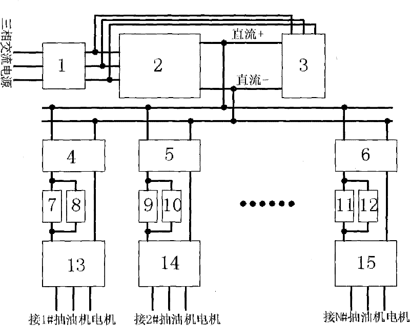
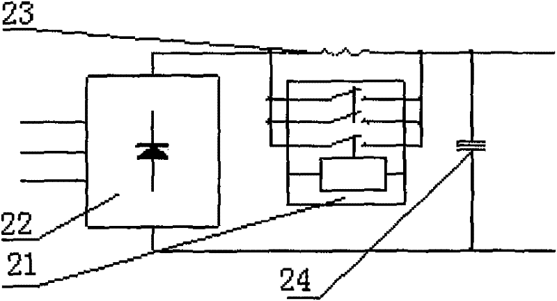
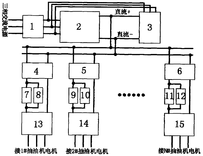
[0030] Such as figure 1 , figure 2 As shown, the pumping unit well site centralized control cabinet of the present invention mainly includes an air switch A 1, a soft start rectifier power supply 2, an energy feedback unit 3, and a sub-well inverter device, and the sub-well inverter device includes N inverter devices , including the first air switch 4, the second air switch 5, the Nth air switch 6, the first unipolar switch 7, the first resistor 8, the second unipolar switch 9, the second resistor 10, and the Nth unipolar switch 11 , the Nth resistor 12, the first inverter power supply 13, the second inverter power supply 14, the Nth inverter power supply 15, and the inverter power supply has a communication interface (RS485 or RS232 or USB). The soft-start rectifier power supply 2 can be selected from a WR-ZLDY type three-phase half-control or full-control rectifier circuit, or through a combination circuit of a three-phase rectifier bridge circuit 22, a resistor A 23, a sw...


PUM


Abstract

The invention relates to a centralized control cabinet for pumping unit well sites. The device includes an air switch A, a soft-start rectifier power supply, a sub-well inverter device, an energy feedback unit, and a housing. The air switch A, soft-start rectifier power supply, sub-well The well inverter device and the energy feedback unit are packaged in the shell, the split well inverter device includes N inverter devices, the air switch A is connected to the soft-start rectifier power supply, and the output of the soft-start rectifier power supply terminal is connected to the input terminal of the energy feedback unit, the output terminal of the energy feedback unit is connected between the air switch A and the soft-start rectifier power supply, and the input terminals of the N inverters are connected to the same bus, the The bus bar is connected to the DC output end of the soft-start rectifier power supply, and the output ends of the N inverters are respectively connected to the N pumping unit motors one by one. Compared with the prior art, the present invention has the advantages of high power saving rate, low failure rate of power grid failure, convenient and cost-saving maintenance, maintenance, and the like.

Description

technical field [0001] The invention relates to a control cabinet, in particular to a centralized control cabinet for pumping unit well sites. Background technique [0002] my country's onshore oilfields are large energy and energy consumers, among which the power consumption of pumping units (commonly known as: kowtow machine) accounts for about one-third of the total power consumption of oil fields! After careful investigation and analysis, we found that the main reason is that 80% of the motor control cabinets of pumping units are still traditional control cabinets designed in the 1970s: basically open circuit + contactor mode. This kind of control cabinet can be said to have only one main function: to manually control the start, operation and stop of the pumping unit. It is not difficult to find that it has the following obvious technical defects: [0003] 1. The protection function is backward or absent: such as power supply phase loss protection, overvoltage protectio...

Claims


Application Information

Patent Timeline
Patent Type & Authority Applications(China)
IPC IPC(8): H02P5/74
Inventor 谭雪开张斌罗林涛罗章勇赵晓华彭志尧
Owner 谭雪开
Why Eureka
Eureka Blog
Learn More