Groove type end mill with double arcs

An end mill, double arc technology, used in milling cutters, manufacturing tools, milling machine equipment, etc., can solve the problems of unusable tools, obstacles to smooth chip discharge, and chips that cannot be curled and broken, so as to reduce chipping and machining. cost, the effect of improving the service life

Active Publication Date: 2012-01-04
ZHUZHOU CEMENTED CARBIDE CUTTING TOOLS CO LTD
View PDF6 Cites 18 Cited by
  • Summary
  • Abstract
  • Description
  • Claims
  • Application Information

AI Technical Summary

Problems solved by technology

If a takes a negative value, the opening of the parabola is inward, that is, the parabola forming the chip flute is a section of convex parabola. Such a groove shape will cause the chips to be unable to curl and break, making the tool unusable
[0008] 4. Due to the existence of two unequal core thicknesses d1 and d2, there will be a sudden change of core thickness step at L1, which hinders the smooth discharge of chips along the chip flute

Method used


Image

  • Groove type end mill with double arcs
  • Groove type end mill with double arcs
  • Groove type end mill with double arcs

Examples


Embodiment Construction

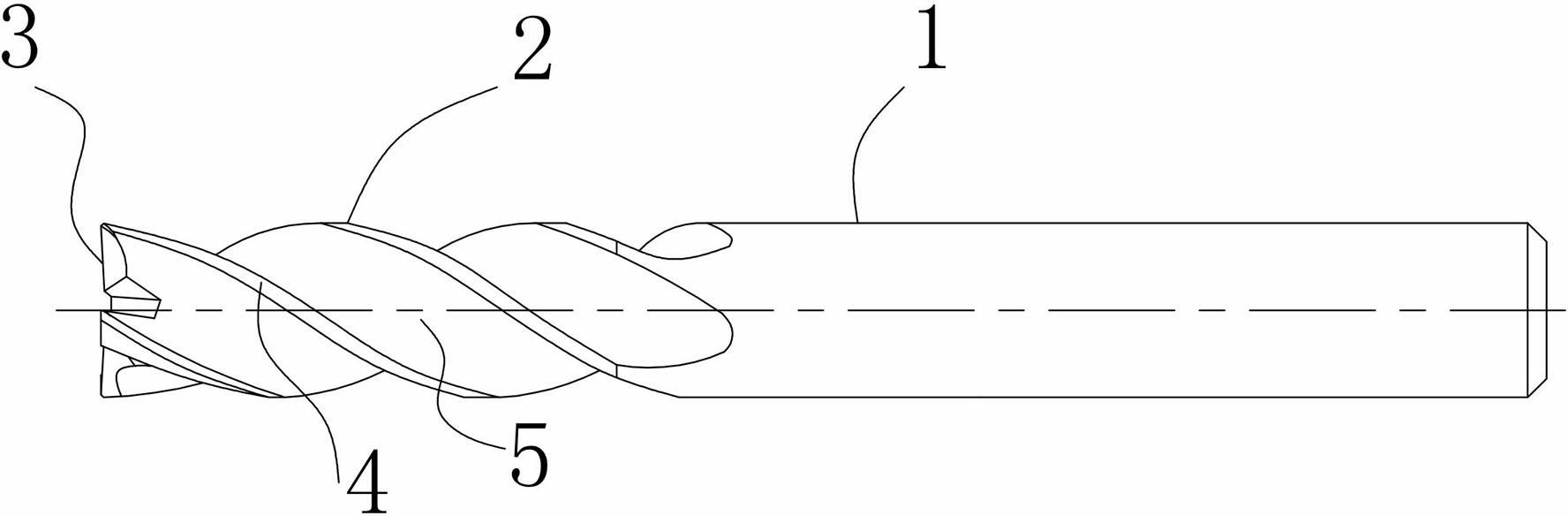
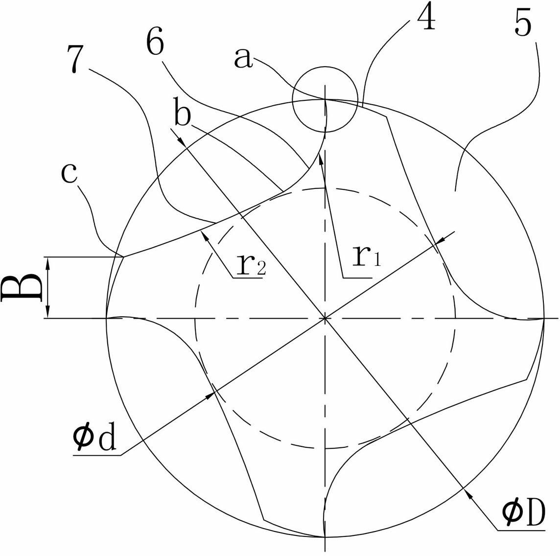
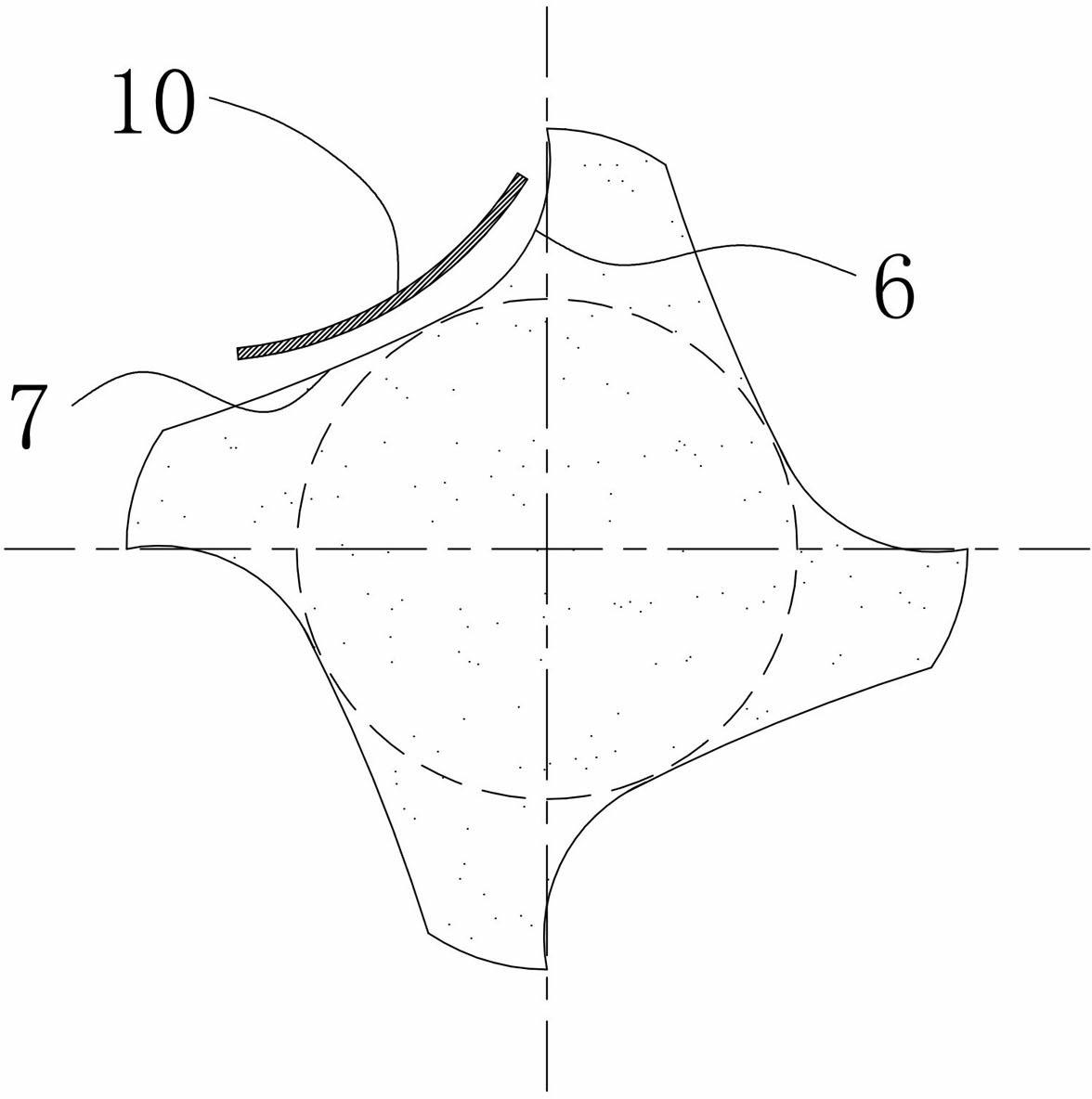
[0025] Figure 1 to Figure 2 It shows an embodiment of an end mill with double arc grooves according to the present invention. The end mill includes a shank 1 and a cutting part 2. The cutting part 2 includes end face cutting teeth 3, peripheral cutting teeth 4 and The chip flute 5 between the adjacent two peripheral cutting teeth 4, the chip flute 5 is composed of and only consists of the groove rake face arc 6 and the groove flank arc 7 in the radial section, and the groove rake face arc 6 passes through points a and b, the groove flank arc 7 passes through points b and c, and the groove flank arc 7 and the groove rake face arc 6 are inscribed at point b, taking the rotation center of the end mill as the origin , the coordinates of all points on the rake face arc 6 satisfy the equation (x-a 1 ) 2 +(y-b 1 ) 2 =r 1 2 , where r 1 is the radius of arc 6 on the rake face of the groove, a 1 and b 1 The value of is not equal to 0; the coordinates of all points on the groov...


PUM


Abstract

The invention relates to a groove type end mill with double arcs. The end mill comprises a handle part and a cutting part, wherein the cutting part comprises an end surface cutting teeth, a peripheral cutting teeth and a chip storage groove. The radial profile of the chip storage groove is formed through a groove front tool face arc and a groove back tool face arc. The groove front tool face arc passes the point a and the point b. The groove back tool face arc passes the point b and the point c. The point b is the inner tangent point of the groove back tool face arc and the groove front tool face arc. With adopting the rotating center of the end mill as the origin, the coordinates of all the points on the groove front tool face arc are meet the following formula: (x-a1)*2+(y-b1)*2=r12, wherein the r1 is the radius of the groove front tool face arc, the a1 is not equal to 0, the b1 is not equal to 0; the coordinates of all the points on the groove back tool face arc are meet the following formula: (x-a2)*2+(y-b2)*2=r22, wherein the r2 is the radius of the groove back tool face arc, the a2 is not equal to 0, the b2 is not equal to 0. The end mill provided by the present invention has characteristics of simple structure, rigidity of the cutting tool, chip accommodation capacity of the cutting tool, and chip discharging capacity of the cutting tool; when the cutting tool is adopted for processing titanium alloy, high temperature alloy, stainless steel and other difficult processing materials, the service life of the cutting tool can be significantly improved, and the cost can be reduced.

Description

technical field [0001] The present invention relates to metal cutting tools, in particular to end mills with double arc grooves. Background technique [0002] In the field of metal cutting, in order to ensure a large chip space, the end mills for rough machining generally require a small core thickness, which will lead to poor tool rigidity and low cutting edge strength; The rigidity of the core requires a large core thickness, which will result in a small chip space for the tool. Therefore, it is difficult for end mills with general structures to meet the requirements of tool rigidity and chip space, especially when processing difficult-to-machine materials such as titanium alloys, high-temperature alloys, and stainless steel. [0003] At present, known integral end mills such as Figure 4 As shown in , the chip flute structure is generally composed of multiple smooth curves, in which there is a groove bottom arc 8 with a small radius. When chips 10 flow through the groove...

Claims


Application Information

Patent Timeline
Patent Type & Authority Applications(China)
IPC IPC(8): B23C5/10
Inventor 倪高明孙振梅左小陈肖思来王社权
Owner ZHUZHOU CEMENTED CARBIDE CUTTING TOOLS CO LTD
Why Eureka
Try Eureka