Body-like node aluminum alloy space truss structure

A network frame structure and aluminum alloy technology, which is applied to building structures, bridge parts, bridge materials, etc., can solve the problems of undiscovered aluminum alloy network frame structure, reduced strength of welded aluminum alloy materials, and high requirements for aluminum alloy welding technology. It achieves the effects of convenient processing and manufacturing, construction and installation, load reduction, and low project life and cost

Inactive Publication Date: 2012-01-04
林娟
View PDF4 Cites 3 Cited by
  • Summary
  • Abstract
  • Description
  • Claims
  • Application Information

AI Technical Summary

Problems solved by technology

[0004] (1) The welding technical requirements of aluminum alloy are high and difficult
[0005] (2) The welded aluminum alloy has the defect that the material strength of the heat-affected zone decreases
[0006] (3) It is not convenient for factory processing and production, and it is not convenient for on-site construction
These "node connector"

Method used


Image

  • Body-like node aluminum alloy space truss structure
  • Body-like node aluminum alloy space truss structure
  • Body-like node aluminum alloy space truss structure

Examples


Embodiment Construction

[0078] The present invention is further described below in conjunction with accompanying drawing.

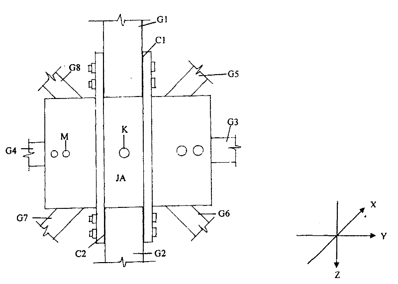
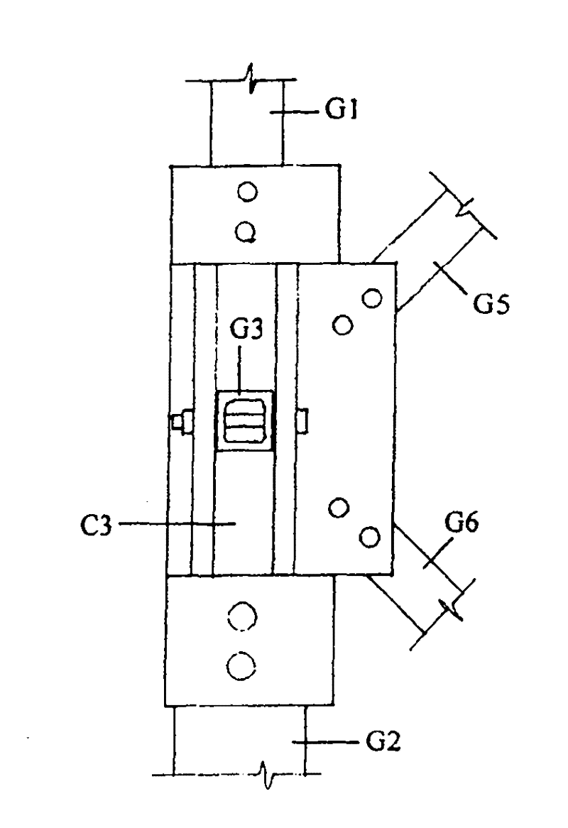
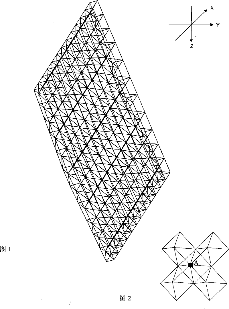
[0079] According to the composition of grid units, the grid structure is generally divided into: plane truss system grid, quadrangular pyramid system grid, and triangular pyramid system grid. figure 1 It is an example of a body-node aluminum alloy orthogonally placed quadrangular pyramid grid structure, figure 2 It is a partial enlargement of the grid structure. All chords, webs and all nodes of the grid frame are made of aluminum alloy. The node structure of the grid structure can all use the planted plate type body nodes, can also use all the planted pole type body nodes, can also use all the planted plate, planted pole hybrid type body nodes, or can be the above three types of body nodes. Nodes are used together. All the rods of the network frame are connected with the node bodies with stainless steel or aluminum alloy bolts or rivets. Rods, node bodies and bolts must b...


PUM


Abstract

A body-like node aluminum alloy space truss structure comprises all body-like space truss node bodies and all space truss chord members and web members, wherein the space truss node bodies are made of aluminum alloy materials, and the space truss chord members and the web members are made of the aluminum alloy materials and connected with the node bodies. The body-like node aluminum alloy space truss structure is characterized in that node body limb plates B1 and B2 connected to the space truss chord members in an X-axis direction are respectively arranged, or node body grooves C1 and C2 connected to the space truss chord members of the x-direction are arranged in positive and negative directions of the X axis located in the plane of the XY axes of the space truss according to requirements of connecting rods on each body-like node body; node body limb plates B3 and B4 connected to the space truss chord members in a Y-axis direction are respectively arranged or node body grooves C3 and C4 connected to the space truss chord members of the Y-direction are arranged in positive and negative directions of the Y axis located in the plane of the XY axes of the space truss; a node body limb plate B5 connected to the space truss web members G5 and G6 is arranged or a node body groove C5 connected to the space truss web members G5 and G6 is arranged in the plane of the space truss web members G5 and G6 at YZ side; and a node body limb plate B6 connected to the space truss web members G7 and G8 is arranged or a node body groove C6 connected to the space truss web members G7 and G8 is arranged in the plane of the web members G7 and G8 at (-Y)Z side. The space truss members converged at a node A(JA) and the space truss member ends corresponding to the node body limb plates are respectively provided with an opening so as to implant the node body limb plate, and the space truss member ends corresponding to the node grooves are directly implanted into the corresponding node grooves.

Description

1. Technical field [0001] The invention relates to a grid structure, which is a spatial grid structure widely used in the fields of house construction, bridge construction and tower structure engineering. 2. Background technology [0002] The flat-plate grid structure, referred to as the grid structure for short, is composed of many rods regularly from two or more directions to form a high-order super-statically indeterminate space structure, which can bear loads from all sides. The structure of the grid frame is light in weight, high in rigidity, good in overall performance and strong in earthquake resistance, and is widely used in large, medium and small span sports buildings, public buildings, plant engineering, hangars, bridge construction, tower engineering and other fields. Bolted ball joint steel grid frame and welded ball joint steel grid frame are steel grid structures widely used in engineering. They use welding as the main manufacturing process. [0003] For alu...

Claims


Application Information

Patent Timeline
IPC IPC(8): E04B1/19E04B1/58E04H12/10E01D19/00E01D101/30
Inventor 林娟梁琨
Owner 林娟
Why Eureka
Try Eureka