
Straw gas heat source engine

A heat source machine and gas technology, applied in the manufacture of combustible gas, heating methods, household heating, etc., can solve the problems of low heating efficiency and waste of energy, and achieve the effect of stable placement, high-efficiency heat source, and increased technological content.

Inactive Publication Date: 2013-04-03
刘玉珂
View PDF5 Cites 0 Cited by
  • Summary
  • Abstract
  • Description
  • Claims
  • Application Information

AI Technical Summary

Problems solved by technology

[0003] The purpose of the present invention is to provide a straw gas heat source machine that can not only continuously burn gas to generate heat, but also rapidly heat circulating water to fully release heat energy, fundamentally solve the problem of low heating efficiency of circulating water in existing straw gas generators, For the problem of wasting energy, the purpose of the design of the present invention is achieved with the structure of double feeding ports and double furnaces, so that the gas can be fully utilized

Method used


Image

  • Straw gas heat source engine

Examples


Embodiment Construction

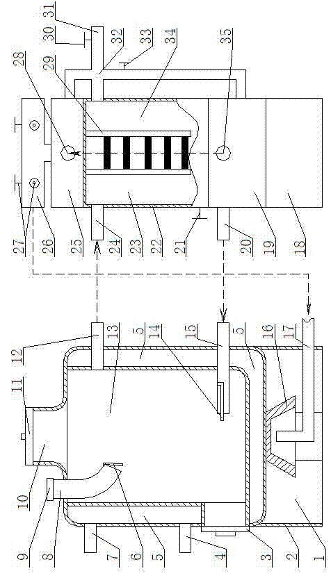
[0023] according to figure 1 The present invention is described in detail.

[0024] The straw gas heat source machine is mainly composed of a gas generator and a gas separator. in:

[0025] The furnace body of the gas generator is respectively provided with two furnaces, i.e. the upper and lower furnaces 13 and 1. The size of the gas generator can be designed according to the amount of heat generated. Generally, the height is 750mm, the diameter is 470mm, and the size of the feeding port is 250mm*150mm. The furnace wall and furnace bottom of the upper hearth are double-layer water injection chambers 5, and the water channels are separated by about two centimeters. The top of the upper furnace 13 is provided with a feeding port 10, and a lock groove sealing furnace cover 11 is provided on the feeding port 10, and a charging port 8 is provided on the furnace shoulder, and a screw cover 9 is provided on the outside, and a valve is provided inside to prevent the leakage of smok...


PUM


Abstract

The invention discloses a straw gas heat source engine, which fundamentally solves the problems of low heating efficiency of circulating water and energy dissipation of the traditional straw gas producer. The straw gas heat source engine comprises a gas producer; and the technical key point is that the straw gas heat source engine also comprises a gas separator. The producer body of the gas producer is respectively provided with an upper producer chamber and a lower producer chamber; the producer wall and the producer bottom of the upper producer chamber are double layers of water pouring cavities; a feed hole is arranged on the top of the upper producer chamber; a material continuing hole is arranged on the producer shoulder of the upper producer chamber; a course gas outlet is arranged on the upper part of the producer wall of the upper producer chamber; and a blast pipe and a sealed producer door are arranged on the lower part of the upper producer chamber, wherein an electric control ignition bar is installed in the blast pipe; the lower producer chamber is formed by hermetically connecting the producer bottom of the upper producer chamber and a support skirt; and a gas stove communicated with an external gas port is arranged in the lower producer chamber. The gas separator comprises a primary clean room, an odorized secondary clean room arranged on the upper part of the primary clean room, an air box arranged on the lower part of the primary clean room and a gas separation room arranged on the top of the odorized secondary clean room. The straw gas heat source engine has the advantages of not only continuously burning produced gas for heat production but also rapidly heating the circulating water for sufficiently releasing the heat energy, and is suitable for production and life.

Description

technical field [0001] The invention relates to a straw gas boiler, in particular to a straw gas heat source machine which integrates gas generation heating and direct-fired gas heating, provides domestic and production hot water, and simultaneously provides straw gas. Background technique [0002] The straw gas generator is to burn the crop straw in the furnace under the condition of anoxic to produce flammable gas mainly carbon monoxide. During the combustion process, the circulating water injected into the double-layer furnace wall and furnace bottom is heated for heating. Facilities, agricultural heating, can also be used for cooking in restaurants, restaurants, canteens, etc., providing heat and fire energy, and straw gas can also be used as power energy after deep processing. In the prior art, the straw gas generator has only one hearth. When in use, it can only rely on the burning of straw in the hearth to heat the circulating water. The heat energy generated is small...

Claims


Application Information

Patent Timeline
Patent Type & Authority Patents(China)
IPC IPC(8): F24B1/183F24B1/191F24B1/197C10J3/20C10J3/84C10J3/72
Inventor 刘玉珂刘莹刘丹
Owner 刘玉珂
Learn More