
Monitoring system and method of heat supply network

A monitoring system and heating network technology, which is applied in heating systems, heating methods, household heating, etc., can solve problems such as the inability to effectively adjust heat energy distribution, and achieve the effect of ensuring maximum utilization, normal pressure, and maintaining flow rate

Inactive Publication Date: 2012-01-04
BEIJING DEBAO HOT TECH
View PDF6 Cites 13 Cited by
  • Summary
  • Abstract
  • Description
  • Claims
  • Application Information

AI Technical Summary

Problems solved by technology

[0004] The purpose of the present invention is to solve the problem that the heating network monitoring system and method in the prior art cannot effectively adjust the overall thermal energy distribution according to different thermal load requirements by using a single control method, and provides a system that can actively perform automatic monitoring according to the operating status of different heating networks. A heating network monitoring system and method that ensures the maximum utilization of heat energy by adjusting the primary side flow and secondary side flow of the heating pipeline through various control methods

Method used

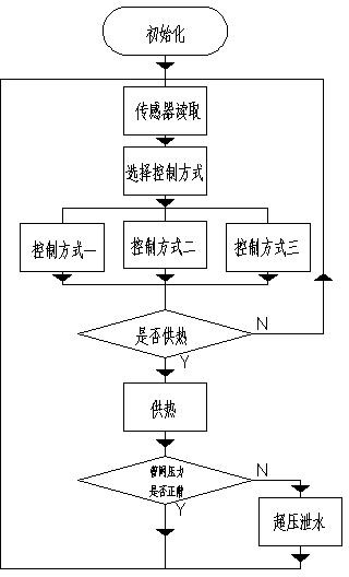
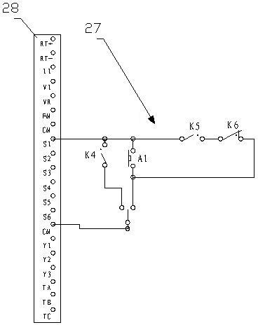

Image

  • Monitoring system and method of heat supply network
  • Monitoring system and method of heat supply network
  • Monitoring system and method of heat supply network

Examples


Embodiment

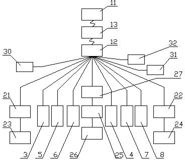
[0029] A heating network monitoring system (refer to attached figure 1 ), this embodiment performs energy-saving control on the heating network. The heating network includes the heating network supervisor, the primary side pipe network supplied by the heat source and multiple secondary side pipe networks directly facing customers. The heat source enters the heating network supervisor, and the heating network supervisor It is connected to the water supply end and return water end of the primary side pipe network, and heat exchange is performed between the primary side pipe network and the secondary side pipe network through a heat exchanger. The secondary side circulation pump 22 of the heating network is arranged on the side pipe network, and the heating network also includes a water supply tank, which can supply water to the secondary side pipe network through the water supply pump 26. In this embodiment, a sub-monitoring system and a host computer 11 Composition, including t...


PUM


Abstract

The invention relates to a monitoring system and method of a heat supply network and can solve the problem of low utilization ratio of heat energy in the prior art. The key point of the technical scheme is as follows: the monitoring system of the heat supply network comprises an upper computer and a sub-monitoring system which comprises a controller, a primary side electric regulating valve, a primary side heat supply network circulating pump speed controller, a secondary side heat supply network circulating pump speed controller and a make-up water pump speed controller; the primary side electric regulating valve is electrically connected with the controller; the controller is electrically connected with a secondary side heat supply network circulating pump via the secondary side heat supply network circulating pump speed controller and is electrically connected with a primary side heat supply network circulating pump via the primary side heat supply network circulating pump speed controller; the make-up water pump speed controller is electrically connected with a make-up water pump; a water make-up startup circuit is connected on the make-up water pump speed controller; a sensorand a heat meter are arranged on the heat supply network and electrically connected with the controller; and the controller communicates with the upper computer via a communication network. The largest utilization ratio of the heat energy can be ensured through various control modes.

Description

technical field [0001] The invention relates to a heating network monitoring system and method, in particular to a system that can actively adjust the primary side flow and secondary side flow of the heating pipeline according to the operating status of different heating networks, and ensure the maximum utilization of heat energy through various control methods High-efficiency heating network monitoring system and method. Background technique [0002] China is a country that consumes a lot of energy, its energy utilization rate is very low, and its energy reserves are obviously insufficient. Most areas in northern my country have long winters. In order to ensure the normal heating of residents, the corresponding heating period is relatively long. Some areas need heating for more than half of the year. The heating industry has become an industry that consumes a lot of energy. In this way, under the premise of ensuring the normal heating of residents, how to respond to the re...

Claims


Application Information

Patent Timeline
IPC IPC(8): F24D19/10
CPCY02B30/745Y02B30/70
Inventor 史扬
Owner BEIJING DEBAO HOT TECH
Learn More