Coupling simple-pendulum experimental device built by using small magnetic steel and measurement method thereof

An experimental device and pendulum technology, applied in educational appliances, instruments, teaching models, etc., can solve the problems of lack of coupled experimental devices and quantitative measurement, difficult to impress college students, and to study experimental principles and experimental content, etc. To achieve good promotion and application prospects, the method is simple, and the effect of easy promotion

Inactive Publication Date: 2012-01-04
BEIJING UNIV OF POSTS & TELECOMM
View PDF4 Cites 19 Cited by
  • Summary
  • Abstract
  • Description
  • Claims
  • Application Information

AI Technical Summary

Problems solved by technology

[0003] However, at present, in the experiments of undergraduates majoring in physics in domestic universities, such experiments are basically limited to the scope of demonstration experiments, and college students are not arranged to participate in quantitative research on related experimental principles and experimental contents. The coupled experimental setup and means of quantitative measurement
Therefore, this kind of experiment can only adopt the method of direct observation, and the experimental phenomenon is relatively simple, it is difficult to impress the college students, and the teaching effect is average.
However, careful and systematic simultaneous research is limited to the field of scientific research, and most of the experimental instruments and equipment are relatively expensive, which is not suitable for undergraduate students.

Method used


Image

  • Coupling simple-pendulum experimental device built by using small magnetic steel and measurement method thereof
  • Coupling simple-pendulum experimental device built by using small magnetic steel and measurement method thereof
  • Coupling simple-pendulum experimental device built by using small magnetic steel and measurement method thereof

Examples


Embodiment Construction

[0033] In order to make the object, technical solution and advantages of the present invention clearer, the present invention will be further described in detail below in conjunction with the accompanying drawings and embodiments.

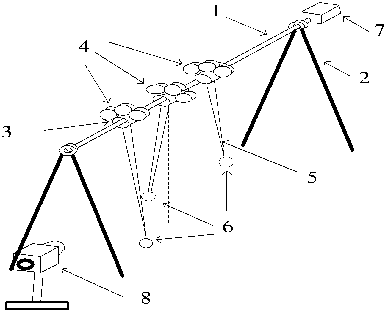
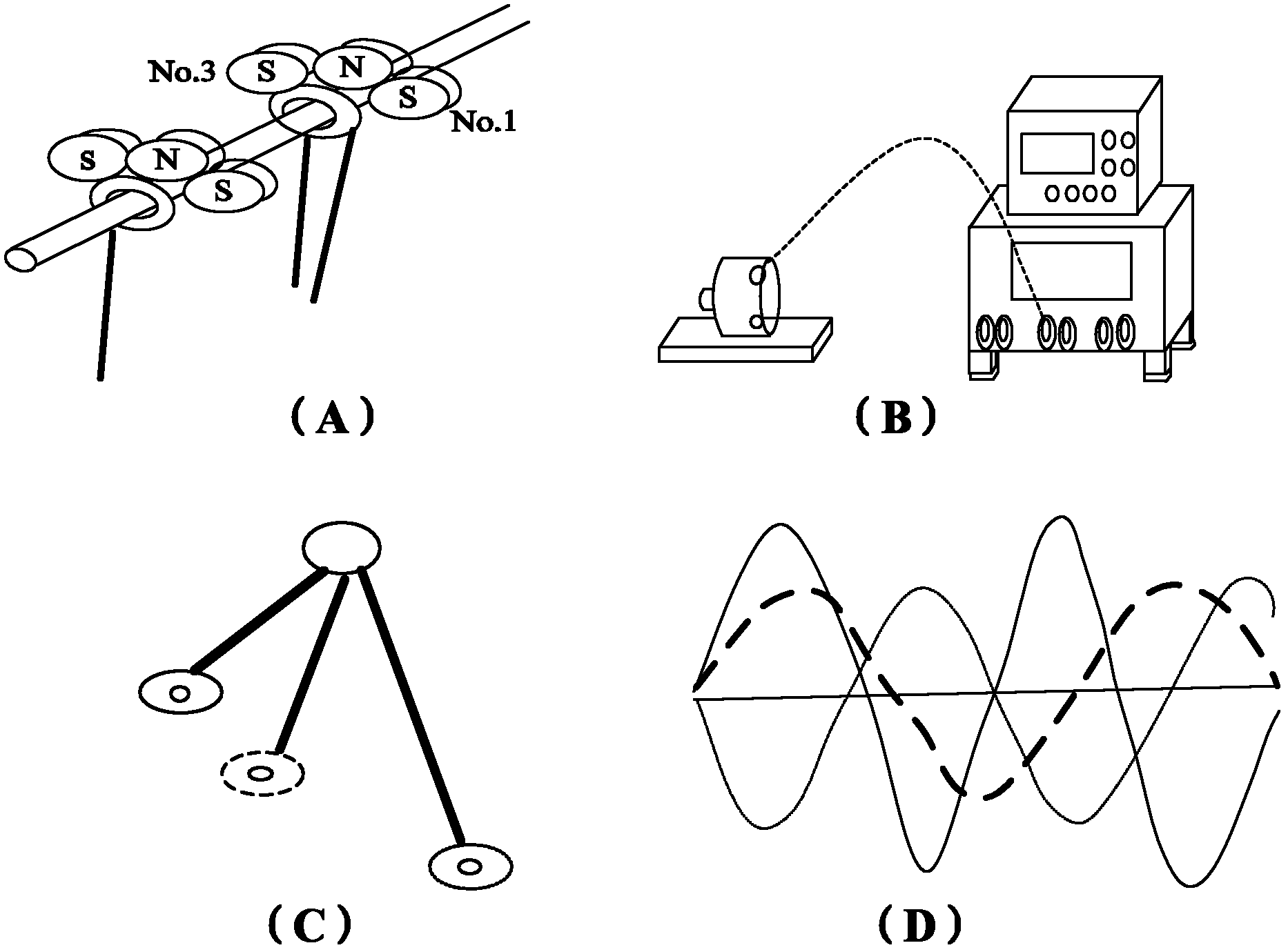
[0034] The present invention utilizes the coupled single pendulum experimental device that small magnetic steel is set up to be based on the coupled pendulum ball resonance demonstrator (EXL-39 type produced by Great Wall Teaching Instrument Co., Ltd., Changchun, China) sold on the market, and additional small magnetic steel, The stepper motor and its controller are modified to study the synchronization of the driving simple pendulum system, and then equipped with a digital camera and a PC. The machine is used to conveniently capture the observation of the coupling synchronization phenomenon and record and analyze the data.

[0035] see Figure 1 ~ Figure 2 , introduce the structural composition and construction process of the experimental device o...


PUM


Abstract

The invention discloses a coupling simple-pendulum experimental device built by using small magnetic steel and a measurement method thereof. The device is obtained by reforming the existing instrument and is provided with a triangular bracket, a rotary shaft, a bearing and multiple shaft sleeves arranged on the rotary shaft at equal interval; a simple pendulum is hung below each shaft sleeve; oneend of the rotary shaft is fixedly connected with a stepping motor; the rotation speed and rotation angle of the stepping motor are adjustable, and the stepping motor can drive the rotary shaft to rotate within a set angle so that each single pendulum is forced to vibrate; one or multiple pieces of small magnetic steel is adsorbed on each shaft sleeve; and the small magnetic steel on adjacent shaft sleeves attracts each other so that the single pendulums influence each other during respective movement to realize coupling. The coupling strength can be changed by changing the amount of the small magnetic steel. A digital camera device can continuously shoot and process the motion images of multiple single pendulums at the same time, and the movement locus, amplitude and other information ofthe coupled single pendulums is displayed, calculated and recorded by a PC (Personal Computer). The device has the advantages of simple structure and low price, and is convenient to operate and easy to popularize.

Description

technical field [0001] The present invention relates to a coupling single pendulum experiment device and measurement method established by using small magnetic steel, to be precise, relates to a multi-pendulum physical experiment device and measurement method using small magnetic steel coupling, which belongs to the physics experiment teaching equipment of colleges and universities and the technical field of experimental methods. Background technique [0002] In the 17th century, the physicist Huygens observed the following phenomenon: when two pendulums of equal length connected together by beams move in stable opposite trends, if there is no or no consideration of energy loss, this motion will always be continue. Huygens called this steady motion synchrony, and attributed it to the slight movement of the beam. It is the slight movement of the beam that establishes the dynamic link between the two pendulums and finally achieves synchronization. Moreover, this connection ...

Claims


Application Information

Patent Timeline
Patent Type & Authority Applications(China)
IPC IPC(8): G09B23/10
Inventor 肖井华李昂杨胡江曾静宜蒋达娅代琼琳
Owner BEIJING UNIV OF POSTS & TELECOMM
Why Eureka
Try Eureka