LED (light-emitting diode) display screen constant-current driving circuit with optional mirror image ratio

An LED display, constant current drive technology, applied in static indicators, instruments, etc., can solve the problems that affect the display quality of full-color LED display, increase the power supply voltage, difficult to build, etc., to improve the driving current and constant current. Accuracy, improved performance, improved display quality

Active Publication Date: 2012-01-04
HEFEI UNIV OF TECH +1
View PDF4 Cites 3 Cited by
  • Summary
  • Abstract
  • Description
  • Claims
  • Application Information

AI Technical Summary

Problems solved by technology

However, since the brightness of a light-emitting diode is determined by the current that drives it, the value of M will be restricted by the constant current accuracy of the drive current and the current consistency between different current drive channels, so it is difficult to establish a very accurate more The system of gray level and brightness contrast relationship, which in turn affects the display quality of the entire full-color LED display
[0004] In addition, in order to improve the overall brightness of the LED display and adapt to the environment with strong light, some LED displays will be designed and produced by stringing sev

Method used


Image

  • LED (light-emitting diode) display screen constant-current driving circuit with optional mirror image ratio
  • LED (light-emitting diode) display screen constant-current driving circuit with optional mirror image ratio
  • LED (light-emitting diode) display screen constant-current driving circuit with optional mirror image ratio

Examples


Embodiment Construction

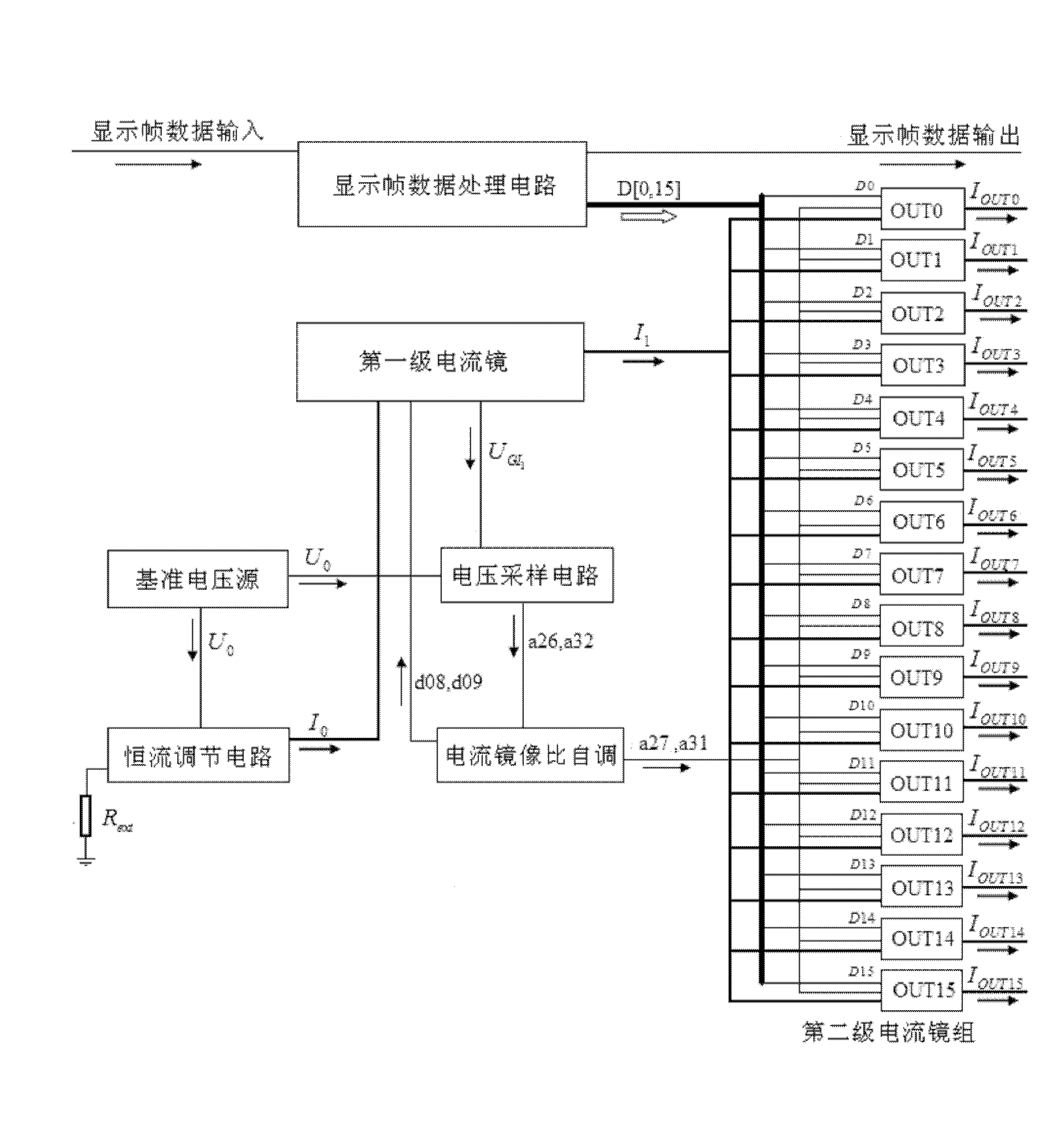
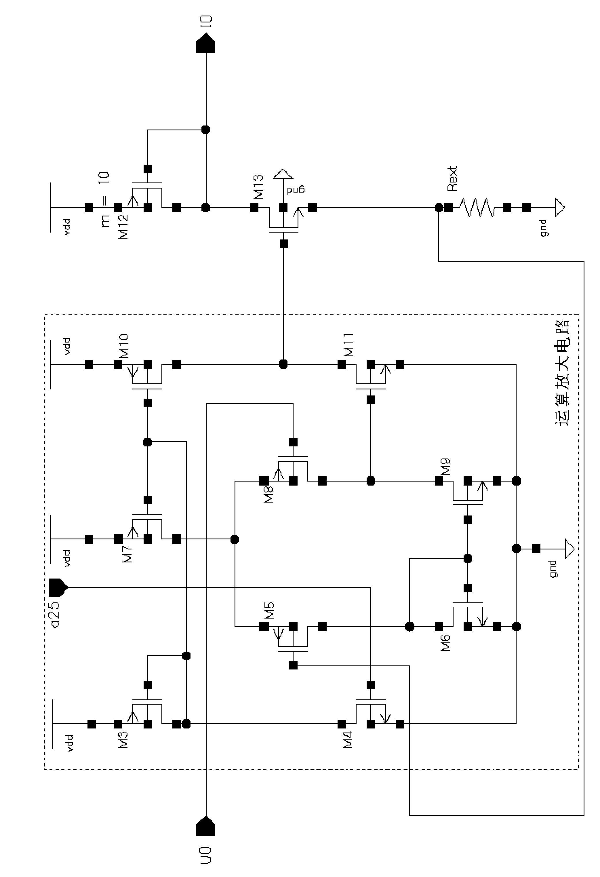
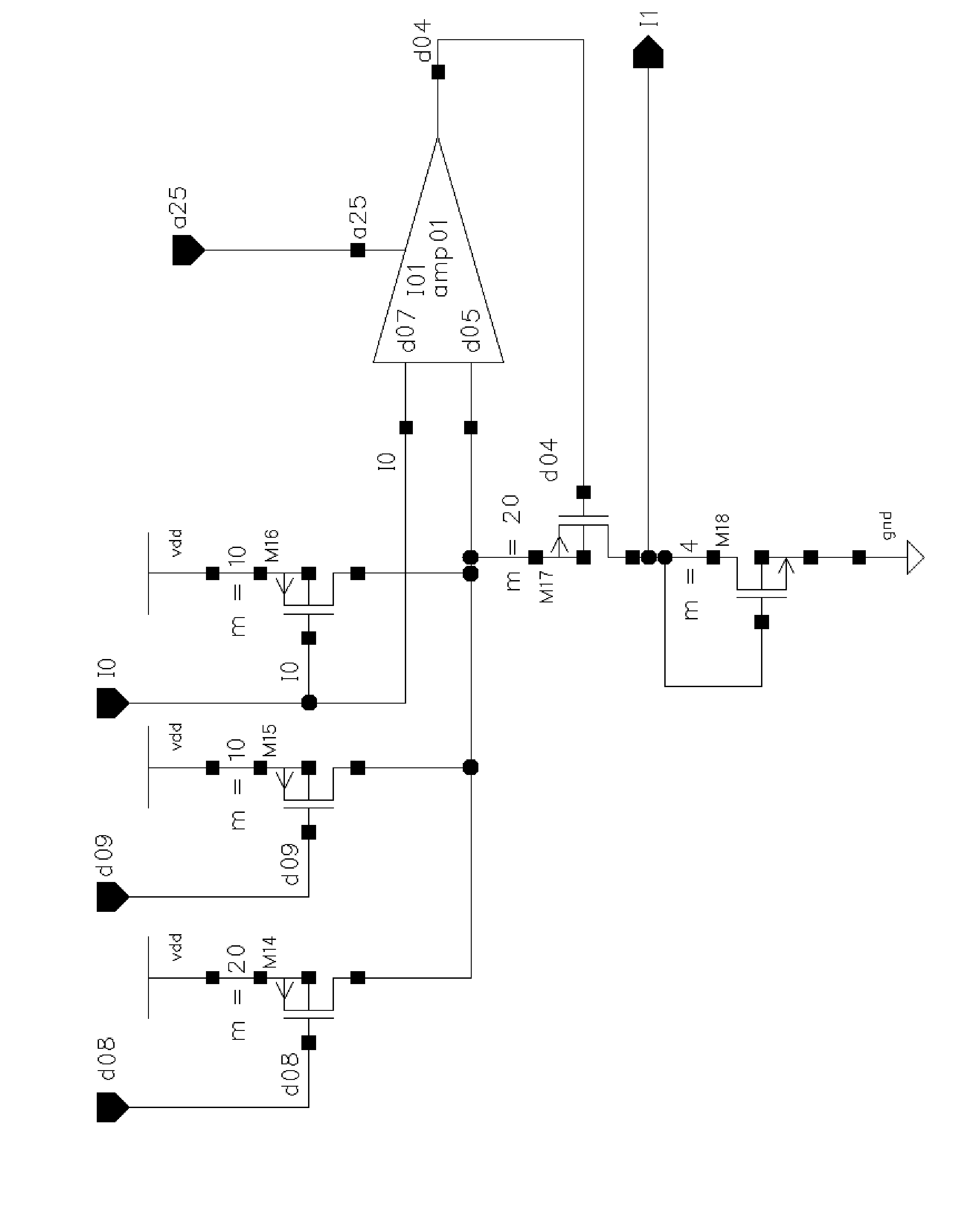
[0028] see Figure 1 to Figure 6 , LED display constant current drive circuit with optional mirror ratio, including reference voltage source circuit, constant current regulation circuit, voltage sampling circuit, current mirror ratio self-adjusting circuit, first-stage current mirror with adjustable mirror ratio, adjustable mirror ratio The second-stage current mirror group and the display frame data processing circuit; the reference voltage source circuit is respectively connected with the constant current regulation circuit and the voltage sampling circuit for generating the reference voltage U 0 , and set the reference voltage U 0 input to the constant current regulation circuit and the voltage sampling circuit respectively; the constant current regulation circuit is connected with the first-stage current mirror, and is used to generate the reference voltage U according to the reference voltage source circuit 0 , generating a constant current I 0 , and the constant curren...


PUM


Abstract

The invention discloses an LED (light-emitting diode) display screen constant-current driving circuit with an optional mirror image ratio. The constant-current driving circuit comprises a reference voltage source circuit, a constant-current adjusting circuit, a voltage sampling circuit, a current mirror image ratio self-adjusting circuit, a current mirror circuit and a display frame data processing circuit, wherein the reference voltage source circuit comprises a seven-loop oscillator and bandgap reference circuit; the constant-current adjusting circuit comprises a comparator, a current offset tube and an external ground resistance; the voltage sampling circuit comprises a differential comparator and a logic processing circuit; the current mirror image ratio self-adjusting circuit comprises a plurality of logic and time sequence circuits; the current mirror circuit comprises a plurality of current mirror image tubes; the display frame data processing circuit comprises a plurality of display frame data processing units; and the output drive channel port of the circuit is provided with a 13V withstand voltage circuit which comprises two NMOS (N-channel metal oxide semiconductor) transistors. The driving circuit provided by the invention has the advantages of increasing the gray levels of the LED display screen, increasing the brightness contrast and solving the withstand problemof the output drive channel port with low cost.

Description

technical field [0001] The invention relates to a driving circuit, in particular to a constant current driving circuit of an LED display screen with self-selected mirror image ratio. Background technique [0002] Light-emitting diode is a current control device, which has the advantages of high brightness, small size, low power consumption, good monochromaticity, fast response speed, and long service life. Large, medium and small LED displays are composed of light-emitting diode arrays, which can be used to display various information such as text, graphics, images, animations, market prices, videos, etc., and light-emitting diodes with three primary colors of red, green and blue The full-color LED display screen composed of it can display delicate color images. In the full-color LED display, in order to improve the display quality of the display and adapt it to various light environments such as day, night, cloudy, sunny, etc., as well as different display backgrounds such...

Claims


Application Information

Patent Timeline
IPC IPC(8): G09G3/32
Inventor 王晓蕾茅俊虎郑皓蒋飞飞
Owner HEFEI UNIV OF TECH
Why Eureka
Try Eureka