Intelligent dimming high-efficiency and constant-current LED drive chip

A technology of LED driving and intelligent dimming, which is applied in the field of lighting, and can solve problems such as inability to adjust light, small dimming range, and incompatible operation of power drivers and dimmers.

Inactive Publication Date: 2014-06-25
无锡汉咏科技股份有限公司
View PDF3 Cites 2 Cited by
  • Summary
  • Abstract
  • Description
  • Claims
  • Application Information

AI Technical Summary

Problems solved by technology

Although this solution is simple in structure, it is generally not possible to use a triac thyristor (TRIAC) dimmer for traditional incandescent lamps to dim LEDs, because the incandescent lamp is a purely resistive load, and the AC / DC power supply The system is quite different from the situation with incandescent lamps
Existing power drivers are not compatible with all types of dimmers, and have low power factor, small dimming range, and often flicker

Method used


Image

  • Intelligent dimming high-efficiency and constant-current LED drive chip
  • Intelligent dimming high-efficiency and constant-current LED drive chip

Examples


Embodiment Construction

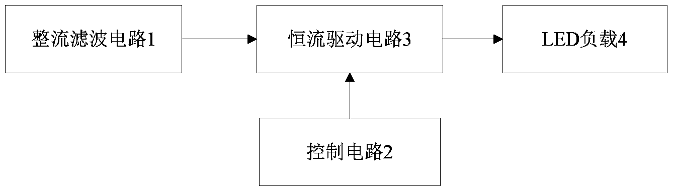
[0017] as attached figure 1 As shown, a schematic block diagram of the principle of an intelligent dimming high-efficiency constant current LED driver chip, EMI filter circuit 1, control circuit 2, chopper circuit 3, flyback conversion circuit 4 and LED load 5, the EMI filter circuit 1 , the chopper circuit 3 , the flyback conversion circuit 4 and the LED load 5 are sequentially connected, and the control circuit 2 is connected to the chopper circuit 3 and the flyback conversion circuit 4 .

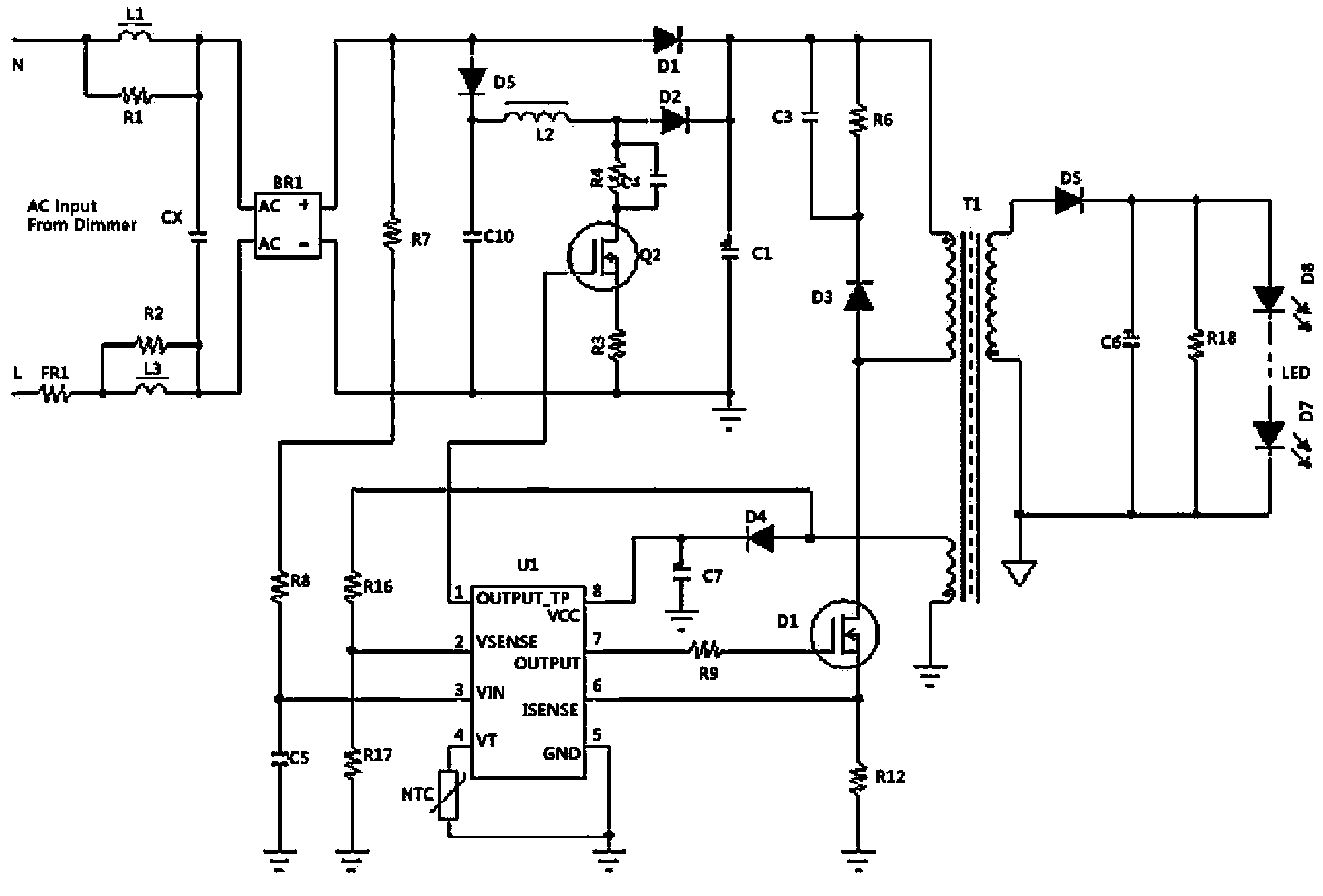
[0018] as attached figure 2 As shown, a circuit design schematic diagram of an intelligent dimming high-efficiency constant current LED driver chip. The control circuit 2 includes a highly integrated high power factor constant current drive LED chip U1, the chip model is iW3610, and the chip pins include OUTPUT_TR, Vsense, VIN, VT, GND, Isense, OUTPUT and VCC; the control circuit 2 It also includes resistors R7, R8, R16, R17, R5, R12, thermistor NTC and MOSFET tube Q1. Resistors R7 and...


PUM


Abstract

The invention discloses an intelligent dimming high-efficiency and constant-current LED drive chip which comprises an EMI filter circuit, a control circuit, a chopper circuit, a flyback transfer circuit and an LED load. The EMI filter circuit, the chopper circuit, the flyback transfer circuit and the LED load are sequentially connected, and the control circuit is connected with the chopper circuit and the flyback transfer circuit. The intelligent dimming high-efficiency and constant-current LED drive chip can detect types and phases of light dimmers through the advanced digital control technique to automatically control the luminance of LEDs, is compatible with various types of light dimmers, is high in constant current accuracy and power factor, has an overtemperature protection function, overvoltage protection function, overcurrent protection function and output current adjustable function and is simple in circuit structure and high in cost performance.

Description

technical field [0001] The invention relates to an LED lighting driving chip, in particular to an intelligent dimming high-efficiency constant current LED driving chip, which belongs to the field of lighting. Background technique [0002] At present, LED lamps have begun to replace various traditional lighting lamps, but the driving power supply of LED itself cannot use the same power supply as ordinary incandescent lamps during the limited period. Because the voltage fluctuation will cause the LED to be damaged due to the increase of the current, so a new power supply must be designed to fully meet the driving requirements of the LED work, so as to maximize the performance of the LED and reduce the occurrence of failures. However, the driving performance of various existing LED driving power sources is not ideal. For example, the output current is easily affected by external voltage fluctuations, which may easily cause damage to the LED and shorten the service life; the cur...

Claims


Application Information

Patent Timeline
Patent Type & Authority Applications(China)
IPC IPC(8): H05B37/02
Inventor 郑云华韩基东
Owner 无锡汉咏科技股份有限公司
Why Eureka
Try Eureka