Laser plasma antenna device

A laser plasma and antenna device technology, applied in the field of antennas, can solve problems such as poor continuity and short plasma channel life, and achieve good results in radio signals

Inactive Publication Date: 2012-01-04
SHANGHAI QIBAO HIGH SCHOOL
View PDF0 Cites 4 Cited by
  • Summary
  • Abstract
  • Description
  • Claims
  • Application Information

AI Technical Summary

Problems solved by technology

However, in the existing literature, although the concept of the laser plasma antenna has been proposed many times, so far no one has reported the realization of this new type of antenna by experiment. The main reason i

Method used


Image

  • Laser plasma antenna device
  • Laser plasma antenna device

Examples


Embodiment Construction

[0010] A preferred embodiment will be given below, and the present invention will be described more clearly and completely in conjunction with the accompanying drawings.

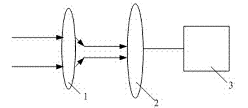
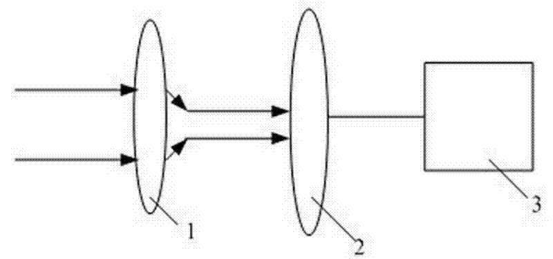
[0011] Such as figure 1 As shown, the laser plasma antenna device of the present invention includes a convex lens 1, a receiver 2 and an oscilloscope 3. The convex lens 1 and the oscilloscope 3 are respectively located on both sides of the receiver 2. The convex lens 1 is a telephoto lens with a focal length of 0.5 meters.

[0012] When the laser is strong enough, it will break down the air and produce plasma. When a laser beam is transmitted in the air, under certain conditions, when the focusing effect caused by the Kerr effect and the defocusing effect caused by diffraction and plasma effects reach a dynamic balance, the laser beam will maintain a long distance. A certain diameter and form a stable plasma channel. In the plasma channel, the originally electrically neutral air molecules are broken down t...


PUM

PropertyMeasurementUnit
Focal lengthaaaaaaaaaa

Abstract

The invention discloses a laser plasma antenna device, which comprises a convex lens, a receiver and an oscilloscope, wherein the convex lens and the oscilloscope are positioned on the two sides of the receiver respectively; laser is focused by the convex lens to form a section of plasma channel on which a radio signal is loaded; the receiver receives the radio signal on the plasma channel; and the radio signal on the plasma channel is reflected on the oscilloscope. According to the laser plasma antenna device, the plasma channel is generated in air, the radio signal is loaded on the plasma channel, and the transmitted radio signal is received by the receiver.

Description

technical field [0001] The invention relates to an antenna, in particular to a laser plasma antenna device. Background technique [0002] Plasma (Plasma) is a system composed of a large number of charged particles. It contains free electrons, free ions, and neutral particles may also exist. It is the fourth state of matter after solid, liquid, and gas. A high-energy aggregate state of matter in an ionized state. Usually, in this condensed state, the negative charge of electrons is equal to the total number of positive charges of ions, and it is neutral macroscopically, so it is called plasma. With the development of science and technology, the application of plasma in various aspects is becoming more and more extensive and in-depth. In addition to industrial applications such as welding, cutting, lighting, metallurgy, chemical industry, and magnetic fluid power generation, plasma is used in microelectricity, optical recording and magnetic recording technology, surface modi...

Claims


Application Information

Patent Timeline
IPC IPC(8): H01Q1/36
Inventor 季忠刚胡金童刘悦珵唐亦昊
Owner SHANGHAI QIBAO HIGH SCHOOL
Why Eureka
Try Eureka