
Electromagnetic wave propagation characteristic test device in low temperature plasma

A technology of low temperature plasma and propagation characteristics, applied in electromagnetic field characteristics, measuring devices, measuring electrical variables, etc., can solve the problems of low control accuracy, difficult to measure electron density, and difficult experiments, to avoid interference phenomenon, reduce difficulty, good repeatability

Inactive Publication Date: 2016-11-16
NANJING SUMAN PLASMA TECH CO LTD
View PDF7 Cites 5 Cited by
  • Summary
  • Abstract
  • Description
  • Claims
  • Application Information

AI Technical Summary

Problems solved by technology

The excitation tube method uses an explosion method to generate a supersonic shock wave, and generates plasma by compressing the gas in the test section. The time for this high-speed shock wave containing plasma to pass through the electromagnetic wave test area is only a few hundred microseconds. Among them, the stable period can only be maintained for about tens of microseconds; since the measurement of electromagnetic wave propagation characteristics must be completed within the stable period, high-speed sampling and timing trigger mechanisms are required, which makes the experiment difficult, inefficient and repeatable; In addition, the cavity used in the excitation tube method is mostly a quartz tube cavity, which is easily damaged and the experimental repeatability is poor.
On the other hand, artificial plasma uses microwaves, electric arcs, and plasma torches to generate plasma. Although it can work for a long time and is relatively stable, due to the high temperature in the environment, its electron density is difficult to measure and the control accuracy is low.

Method used


Image

  • Electromagnetic wave propagation characteristic test device in low temperature plasma
  • Electromagnetic wave propagation characteristic test device in low temperature plasma
  • Electromagnetic wave propagation characteristic test device in low temperature plasma

Examples


Embodiment Construction

[0023] A specific embodiment of the present invention will be described in detail below in conjunction with the accompanying drawings. These drawings are all simplified schematic diagrams, which only schematically illustrate the basic structure of the present invention, so they only show the configurations related to the present invention.

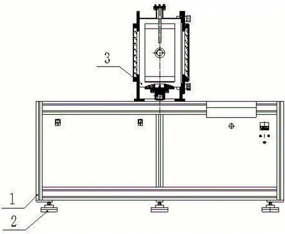
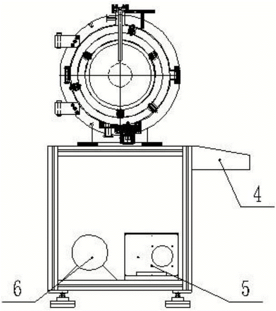
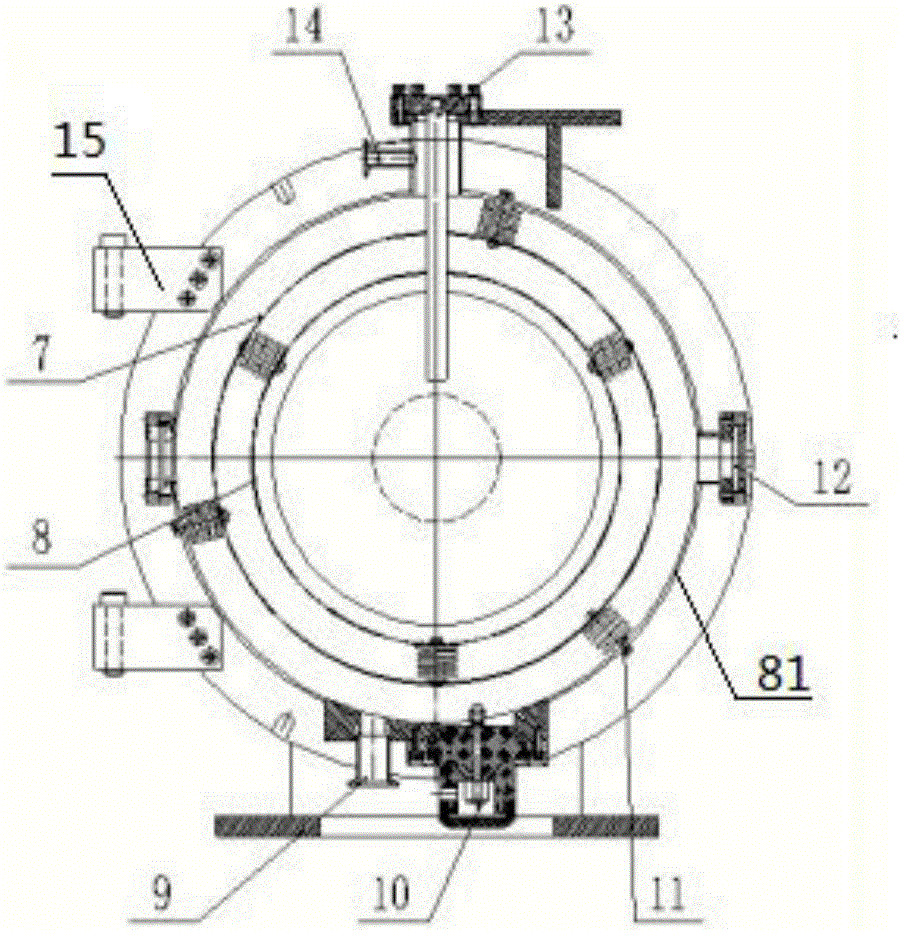
[0024] A device for testing electromagnetic wave propagation characteristics in low-temperature plasma, specifically as Figure 1-3 As shown, it includes: a control cabinet 1 and a plasma generation chamber 3 fixedly arranged at the center above the cabinet body; the plasma generation chamber 3 is provided with a ring-shaped high-voltage electrode 7, an inner ring-shaped ground electrode 8 and The outer ring-shaped ground electrode 81, the inner ring-shaped ground electrode 8 and the outer ring-shaped ground electrode 81 are set concentrically; wherein, the ring-shaped high-voltage electrode 7 is arranged on the inner ring-shaped ground ele...


PUM


Abstract

The invention provides an electromagnetic wave propagation characteristic test device in low temperature plasma. The device comprises a plasma generation chamber, an annular high-voltage electrode and an annular ground electrode, wherein the annular high-voltage electrode and the annular ground electrode are arranged in the plasma generation chamber. The annular high-voltage electrode and the annular ground electrode are in insulation connection. The annular ground electrode is fixedly connected with the inner wall of the plasma generation chamber. The device uses the technology that electric potential difference is prevented inside plasma generated by glow discharge at low air pressure is used; the stable period of the generated plasma is prolonged, which is favorable for studying the propagation characteristic of electromagnetic waves of various frequency bands in the plasma; a good experiment environment is provided for studying absorption and scattering of incident electromagnetic waves of the plasma, tracking and identification technologies of a space exploration spacecraft which comes into atmosphere again, a plasma stealth technology, a plasma de-noising technology, a plasma antenna technology and the like; and the device has high scientific experimental application value and market prospect.

Description

technical field [0001] The invention belongs to the technical field of radio wave propagation experiments, and in particular relates to a device for testing electromagnetic wave propagation characteristics in low-temperature plasma. Background technique [0002] Plasma is composed of free electrons, positive ions and neutral atoms with equal charges, and is the fourth state of matter. As a special dispersion medium, plasma has unique absorption, reflection and scattering characteristics for electromagnetic waves; when electromagnetic waves propagate in plasma, its electric field will exert force on free electrons and positive ions, thus affecting the electromagnetic waves in plasma. The propagation characteristics of the plasma, especially the absorption and scattering of the incident plane wave by the plasma, are of great importance to the exploration of re-entry object tracking and identification technology, plasma stealth technology, plasma noise reduction technology and ...

Claims


Application Information

Patent Timeline
IPC IPC(8): G01R29/08
CPCG01R29/0871
Inventor 万良庆陈选章
Owner NANJING SUMAN PLASMA TECH CO LTD
Learn More