Metal film production apparatus

Inactive Publication Date: 2006-05-25
CANON ANELVA CORP
View PDF5 Cites 4 Cited by
  • Summary
  • Abstract
  • Description
  • Claims
  • Application Information

AI Technical Summary

Benefits of technology

[0007] The present invention has been accomplished in light of the circumstances described above. The present invention provides a metal film production apparatus and a m

Problems solved by technology

With the above-mentioned conventional technique, it has been difficult to increase the speed of film formation, because the film is formed with the use of a thermal reaction.
Moreover, the metal complex as the start

Method used


Image

  • Metal film production apparatus
  • Metal film production apparatus
  • Metal film production apparatus

Examples


second embodiment

[0050] The metal film production apparatus shown in FIG. 5 is the metal film production apparatus shown in FIG. 1 provided with an etched member having a different shape. That is, an etched member 21 made of a metal (Cu) is held between the opening at the upper surface of the chamber 1 and the ceiling board 7. The etched member 21 has a ring portion 22 fitted to the opening at the upper surface of the chamber 1, the ring portion 22 being in the form of a short cylinder having the same diameter as the diameter of the chamber 1.

first embodiment

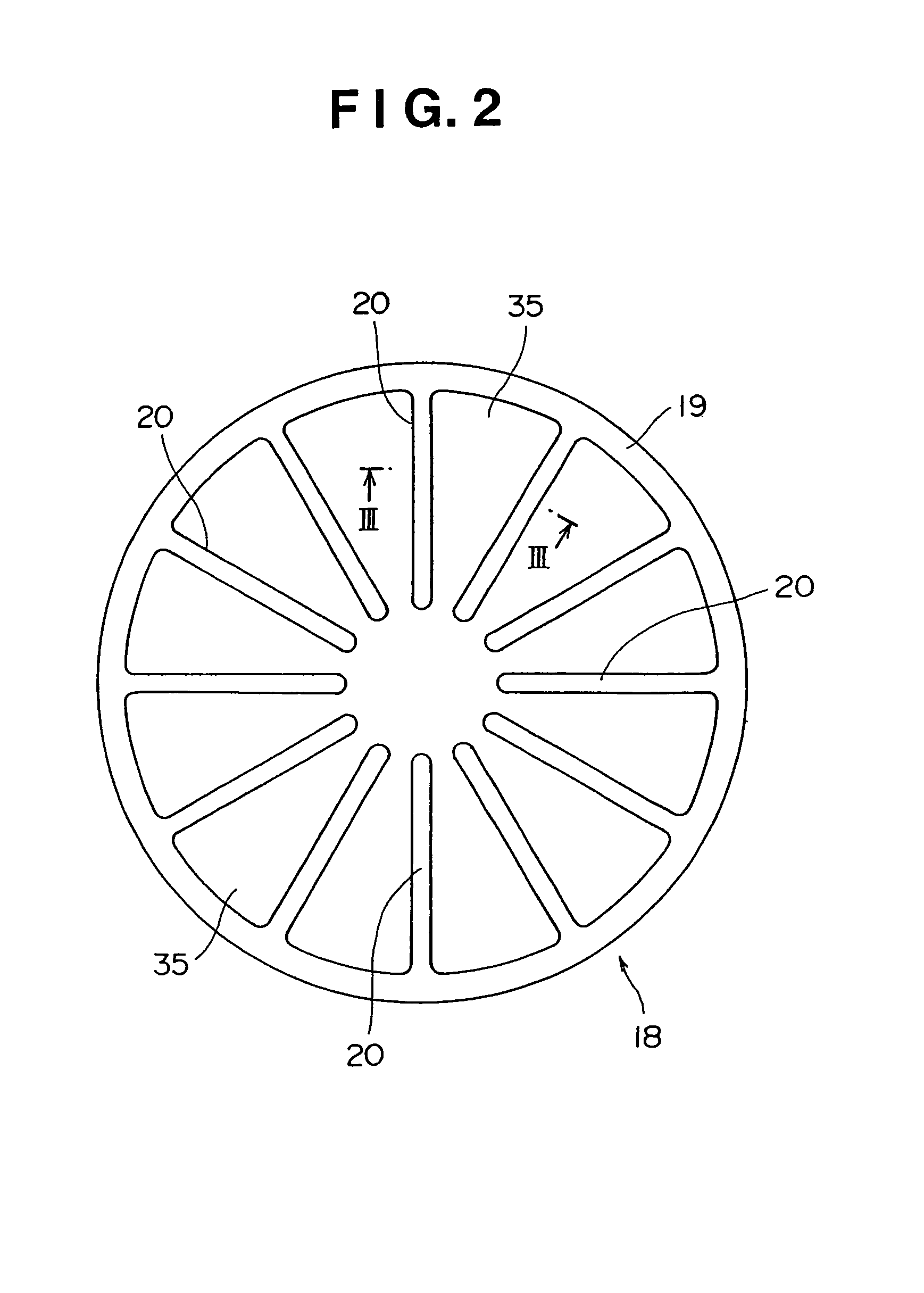
[0051] A plurality of protrusions 23, which extend close to the center in the diametrical direction of the chamber 1, have the same width, and have a lower surface inclined upward and a thickness progressively decreased in an upward direction, are provided in the circumferential direction on the inner periphery of the ring portion 22. For example, the thickness of the front end of the protrusion 23 is set at about a fourth to fifth of the thickness of the ring portion 22. The ring portion 22 is earthed, and the plural protrusions 23 are electrically connected together and maintained at the same potential (same potential maintaining means). Notches (spaces) are present between the protrusions 23 in the same manner as in the

[0052] A sheath heater 24 is provided in the protrusion 23, and the temperature of the protrusion 23 is controlled by a thermocouple 25 (sensor) to a predetermined temperature higher than the temperature of the substrate 3 (the action of temperature control means)....

third embodiment

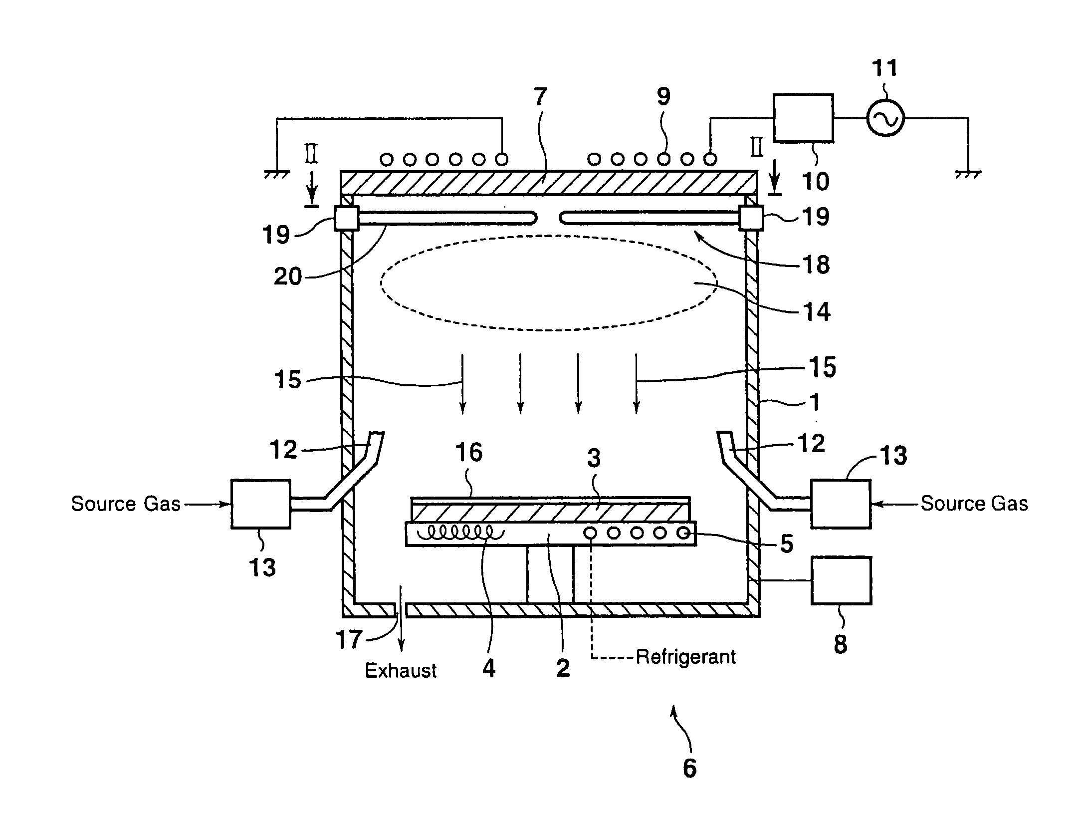
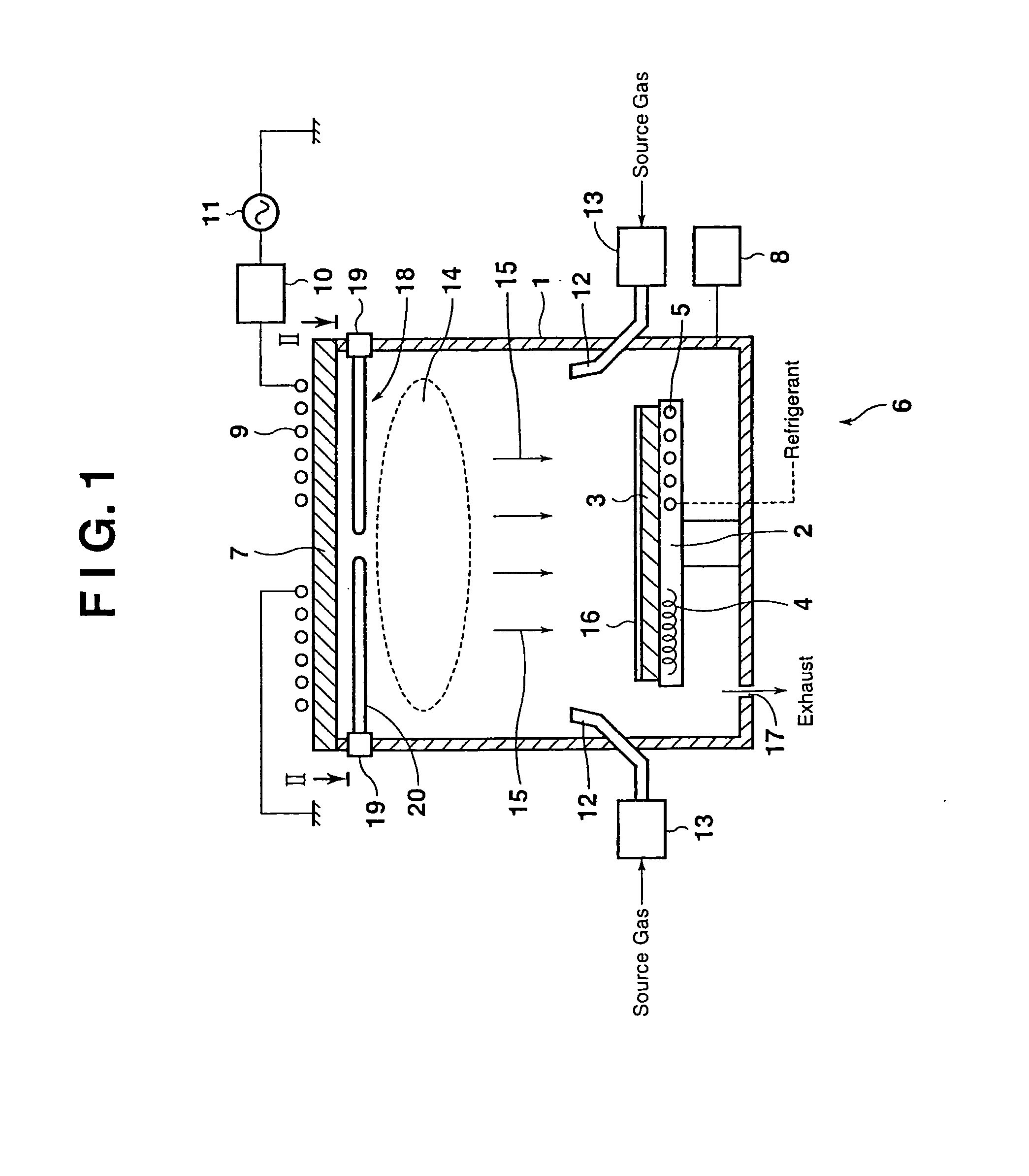
[0058] The metal film production apparatus shown in FIG. 6 is different from the metal film production apparatus shown in FIG. 1 in that the nozzles 12 and the flow controllers 13 at the lower portion of the chamber 1 are not provided. A gas passage 26 is formed in the center of the protrusion 20, and gas ejection holes 27 communicating with the gas passage 26 are formed at the front end of the protrusion 20 and at suitable positions in a lower area of the protrusion 20. A source gas is supplied from a flow controller 13 to the gas passage 26.

[0059] With the above-described metal film production apparatus, the source gas is supplied to the interior of the chamber 1 through the gas ejection holes 27 of the protrusions 20, and electromagnetic waves are shot from the plasma antenna 9 into the chamber 1. As a result, the Cl2 gas is ionized to generate a Cl2 gas plasma (source gas plasma) 14. The etched member 18, an electric conductor, is present below the plasma antenna 9. However, th...


PUM


Abstract

A source gas is supplied into a chamber through a nozzle, and electromagnetic waves are thrown from a plasma antenna into the chamber. The resulting Cl2 gas plasma causes an etching reaction to a plurality of copper protrusions, which are arranged between a substrate and a ceiling member in a discontinuous state relative to the flowing direction of electricity in the plasma antenna, to form a precursor (CuxCly). The precursor (CuxCly) transported toward the substrate controlled to a lower temperature than the temperature of an etched member is converted into only Cu ions by a reduction reaction, and directed at the substrate to form a thin Cu film on the surface of the substrate. The speed of film formation is fast, the cost is markedly decreased, and the resulting thin Cu film is of high quality.

Description

CROSS-REFERENCE TO RELATED APPLICATIONS [0001] This application is a Divisional of co-pending application Ser. No. 10 / 277,207, filed on Oct. 22, 2002, the entire contents of which are hereby incorporated by reference and for which priority is claimed under 35 U.S.C. § 120.BACKGROUND OF THE INVENTION [0002] 1. Field of the Invention [0003] This invention relates to a metal film production apparatus and a metal film production method of producing a metal film on the surface of a substrate by a vapor phase growth method. [0004] 2. Description of Related Art [0005] In preparing a metal film, such as a thin film of copper, by the vapor phase growth method, it has been common practice to use an organometallic complex of a liquid, for example, copper-hexafluoroacetylacetonato-trimethylvinylsilane, as a starting material, dissolve the solid starting material in a solvent, and vaporize the solution by use of a thermal reaction to form a film on a substrate. [0006] With the above-mentioned co...

Claims


Application Information

Patent Timeline
IPC IPC(8): C23C16/00H01L21/31C23C16/507C23C16/06C23C16/08C23C16/14C23C16/448C23C16/455H01J37/32H01L21/285
CPCC23C16/14C23C16/4488H01J2237/2001H01J37/321C23C16/455C23C16/06
Inventor MATSUDA, RYUICHIYAHATA, NAOKISAKAMOTO, HITOSHI
Owner CANON ANELVA CORP
Why Eureka
Try Eureka