Spline lubricating structure
A lubricating structure and spline technology, applied in the transmission field, can solve the problems of inability to guarantee the oil quantity of the spline, the failure rate of the spline is increased, and the lubrication of the spline is not ideal, so as to achieve a simple structure, good lubrication effect, and simplify the lubrication oil path Effect
- Summary
- Abstract
- Description
- Claims
- Application Information
AI Technical Summary
Problems solved by technology
Method used
Image

Examples
Embodiment 1
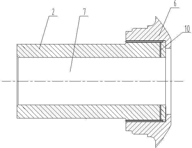
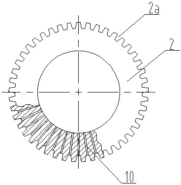
[0034] Embodiment 1: as figure 1 and figure 2 As shown, a spline lubricating structure is used for the gearbox transmission of a rolling machine, including a spline shaft 2 and a spline sleeve 6 that cooperate with each other. The spline shaft 2 is provided with an inner hole 7 and a radial oil hole 10 . The number of oil holes 10 is equal to the number of tooth grooves of the spline shaft 2 , and are evenly distributed along the circumferential direction of the inner hole 7 . The oil inlet of each oil hole 10 is arranged in the inner hole 7, and the oil outlet is respectively arranged at each tooth groove 2a.
[0035] When the spline shaft 2 is working, it rotates and injects lubricating oil into the inner hole 7. The lubricating oil flows from one end of the inner hole 7 to the other. Due to the centrifugal force, when the lubricating oil passes through the oil inlet of the oil hole 10, it is thrown away. Into the oil hole 10, so as to flow into the tooth groove 2a of th...
Embodiment 2
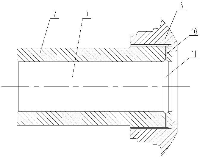
[0036] Embodiment 2: as image 3 As shown, the structure of this embodiment is basically the same as that of Embodiment 1, the difference is that an oil collector ring groove 11 is provided at the oil inlet corresponding to the oil hole 10 .
[0037] Other structures and working principles of this embodiment are the same as those of Embodiment 1. Due to the setting of the oil collecting ring groove 11, when the lubricating oil flows through the oil collecting ring groove 11, it will accumulate in the oil collecting ring groove 11 to form a certain liquid level height, which is beneficial for the lubricating oil to be thrown into the oil hole 10, Achieve more adequate oil supply.
Embodiment 3
[0038] Embodiment 3: as Figure 4 and Figure 5 As shown, a spline lubrication structure is used in a planetary gearbox, including a spline shaft 2 and a spline sleeve 6 that cooperate with each other. The spline shaft 2 is provided with an inner hole 7 , and an oil collector ring groove 11 is arranged in the inner hole 7 . The spline sleeve 6 is provided with a ring groove 9, and the spline shaft 2 and the spline sleeve 6 correspond to the ring groove 9 to form an oil collection chamber 14. The spline shaft 2 is provided with three sections of oil holes connected end to end, the oil holes at two adjacent ends are perpendicular to each other, and the oil passages 10 are formed by the three sections of oil holes. The oil inlet of the oil passage 10 is arranged at the oil collecting ring groove 11 , and the oil outlet is arranged at the oil collecting chamber 14 .
[0039] The working principle of this embodiment is basically the same as that of Embodiment 2. The difference i...
PUM
 Abstract
Description
Claims
Application Information
 - R&D
- Intellectual Property
- Life Sciences
- Materials
- Tech Scout
- Unparalleled Data Quality
- Higher Quality Content
- 60% Fewer Hallucinations
Browse by: Latest US Patents, China's latest patents, Technical Efficacy Thesaurus, Application Domain, Technology Topic, Popular Technical Reports.
© 2025 PatSnap. All rights reserved.Legal|Privacy policy|Modern Slavery Act Transparency Statement|Sitemap|About US| Contact US: help@patsnap.com