Lubricating and cooling combined structure of engine piston and connecting rod group

A piston connecting rod, lubrication and cooling technology, applied in the direction of engine cooling, engine lubrication, engine components, etc., can solve the problems of scratched connecting rod small end bushing, insufficient piston cooling, low oil pressure, etc., to achieve lubrication And the effect of high cooling efficiency, simple design, high oil flow rate

Active Publication Date: 2017-08-25
HENAN DIESEL ENGINE IND
View PDF1 Cites 0 Cited by
  • Summary
  • Abstract
  • Description
  • Claims
  • Application Information

AI Technical Summary

Problems solved by technology

The pistons of many existing engines use cooling nozzles to supply oil for cooling. For example, the patent "An All-steel Piston with an Introduced Cooling Oil Chamber" (CN202883148U) adopts this structure. The cooling nozzles are installed on the body, and the pistons are reciprocating. Among them, the distance between the nozzle and the oil inlet hole of the piston varies from time to time, and the amount of oil sprayed into the piston cooling chamber is sometimes too much, and the cooling of the piston is not sufficient; Small particles may cause nozzle blockage, and serious blockage will cause the piston to scuff the cylinder
The bushing at the small end of the connecting rod and the piston pin are usually lubricated by splashing. The lubricating oil usually comes from the engine oil scraped off by the piston ring from the cylinder liner. The oil pressure is low, the flow rate is slow, and it is easy to entrain the metal shavings scraped off by the piston ring from the cylinder liner. Then scratch the small end bushing of the connecting rod

Method used


Image

  • Lubricating and cooling combined structure of engine piston and connecting rod group
  • Lubricating and cooling combined structure of engine piston and connecting rod group

Examples


Embodiment Construction

[0023] The present invention is described in conjunction with accompanying drawing and specific embodiment:

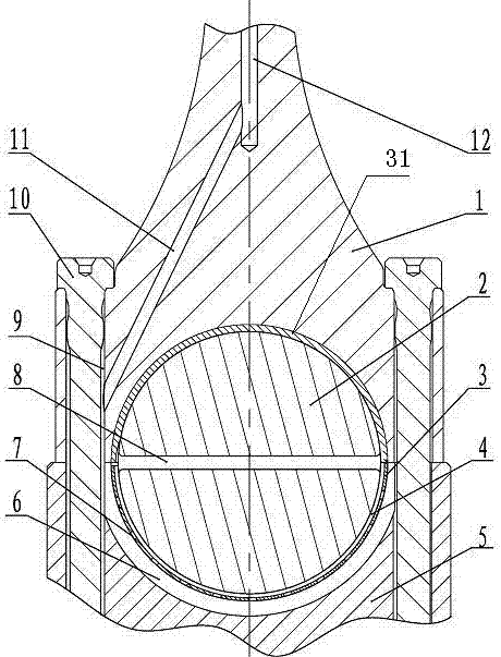
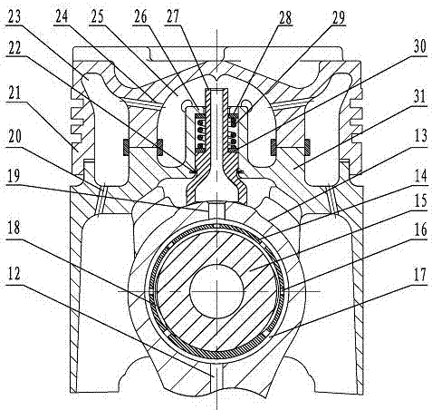
[0024] Such as figure 1 , figure 2Shown, a kind of lubricating and cooling combined structure of engine piston connecting rod group, piston connecting rod group includes piston, piston pin 15 and connecting rod; The connecting rod small end 13 of described connecting rod passes piston pin 15 and described Piston connection; a connecting rod small end bushing 14 is arranged between the piston pin 15 and the small end 13 of the connecting rod; the semicircular hole at the large end of the connecting rod shaft 1 and the semicircular hole of the connecting rod cover Two semicircular upper connecting rod bearing bushes 32 and lower connecting rod bearing bushes 3 are embedded respectively. The upper and lower connecting rod bearing bushes are installed on the connecting rod journal 2 of the crankshaft and are clearance-fitted with the connecting rod journal 2. The connect...


PUM


Abstract

The invention belongs to the technical field of machinery and proposes a lubricating and cooling combined structure of an engine piston connecting rod group. A combined lubricating and cooling structure for an engine piston and connecting rod group proposed includes a connecting rod lubricating structure and a piston cooling structure; the connecting rod lubricating structure has a connecting rod journal oil hole (8) located on the connecting rod journal of the crankshaft; The rod journal oil hole (8) is a radial through hole located on the connecting rod journal of the crankshaft and communicates with the main oil passage of the diesel engine; the upper end of the small end of the connecting rod (13) is provided with a guide for communicating with the piston cooling structure. The oil jacket (27); the inner cooling cavity (25) of the piston cooling structure; the upper end outlet of the oil guide sleeve (27) is located in the inner cooling cavity (25); the outer cooling cavity (25) is provided with an outer cooling cavity ( twenty three). The cooling of the piston and the lubricating of the connecting rod in the invention share the same engine oil passage, the design is simpler, the reliability is higher, and the lubricating and cooling efficiency is high.

Description

technical field [0001] The invention belongs to the technical field of machinery and relates to a lubricating and cooling combined structure of an engine piston connecting rod group. Background technique [0002] The piston connecting rod group is an important transmission part of the engine. It transmits the pressure of the combustion gas to the crankshaft, making the crankshaft rotate and output power. The piston connecting rod group is composed of pistons, piston rings, piston pins, connecting rods and other parts; pistons and cylinders The cover constitutes the combustion chamber, bears the gas expansion pressure, transmits the power to the crankshaft through the piston pin and the connecting rod, and is driven by the connecting rod to complete the three auxiliary strokes of intake, compression and exhaust; [0003] The piston consists of two parts, the head and the skirt. The piston head is cut with a number of annular grooves for the installation of piston rings. The...

Claims


Application Information

Patent Timeline
Patent Type & Authority Patents(China)
IPC IPC(8): F01M1/06F01P3/10F02F3/22
Inventor 王黎明王正祥董飞莹昂扬
Owner HENAN DIESEL ENGINE IND
Why Eureka
Try Eureka