Gas-liquid combined hydraulic impacter

A hydraulic impactor, gas-liquid combination technology, applied in the directions of portable impact tools, striking tools, fluid pressure actuating devices, etc., can solve the problems of large back pressure resistance in the front cavity, vibration and noise, affecting the working life of valves and pistons, etc. , to achieve the effect of high energy utilization rate, long working life, and sufficient fuel supply.

Inactive Publication Date: 2012-08-15
CHANGSHA UNIVERSITY OF SCIENCE AND TECHNOLOGY
View PDF3 Cites 1 Cited by
  • Summary
  • Abstract
  • Description
  • Claims
  • Application Information

AI Technical Summary

Problems solved by technology

[0003] The existing impact device based on the principle of hydraulic-nitrogen combined action is because the hydraulic impact device adopts the piston oil distribution method of double-sided oil inlet and discharge. The instantaneous peak flow rate is large, and the back pressure resistance of the front cavity is large during the piston stroke. On the other hand, the pressure oil in the push valve cavity of the reversing valve is directly supplied by the front cavity or the rear cavity of the piston cylinder, but because the valve core is in the process of reversing movement, The opening of the valve port of the oil chamber will undergo a movement change process from large to small and then from small to large, that is, when the spool moves to the middle position, the opening of the oil inlet chamber valve port is the smallest, and at this time the spool moves at the highest speed , the oil supply required for the push valve cavity is also the largest, which is contradictory, which will cause a serious shortage of oil supply for the push valve cavity, forming a "vacuum suction" phenomenon, causing hydraulic shock, vibration and noise, which will seriously affect the valve and piston. the working life of the impactor, and cause the impactor to work unstable, for this reason, structural measures must be taken to solve it

Method used


Image

  • Gas-liquid combined hydraulic impacter
  • Gas-liquid combined hydraulic impacter
  • Gas-liquid combined hydraulic impacter

Examples


Embodiment Construction

[0015] A specific implementation of a gas-hydraulic combined hydraulic impactor will be described in detail below with reference to the accompanying drawings.

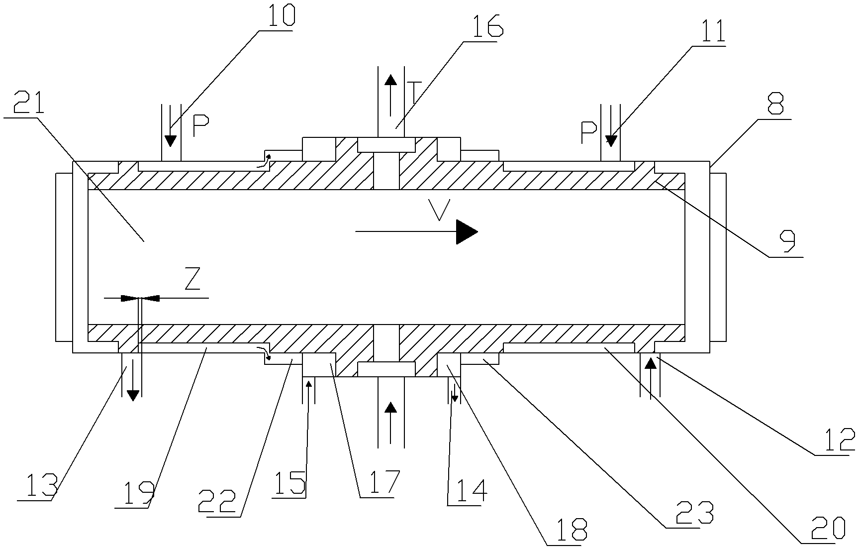
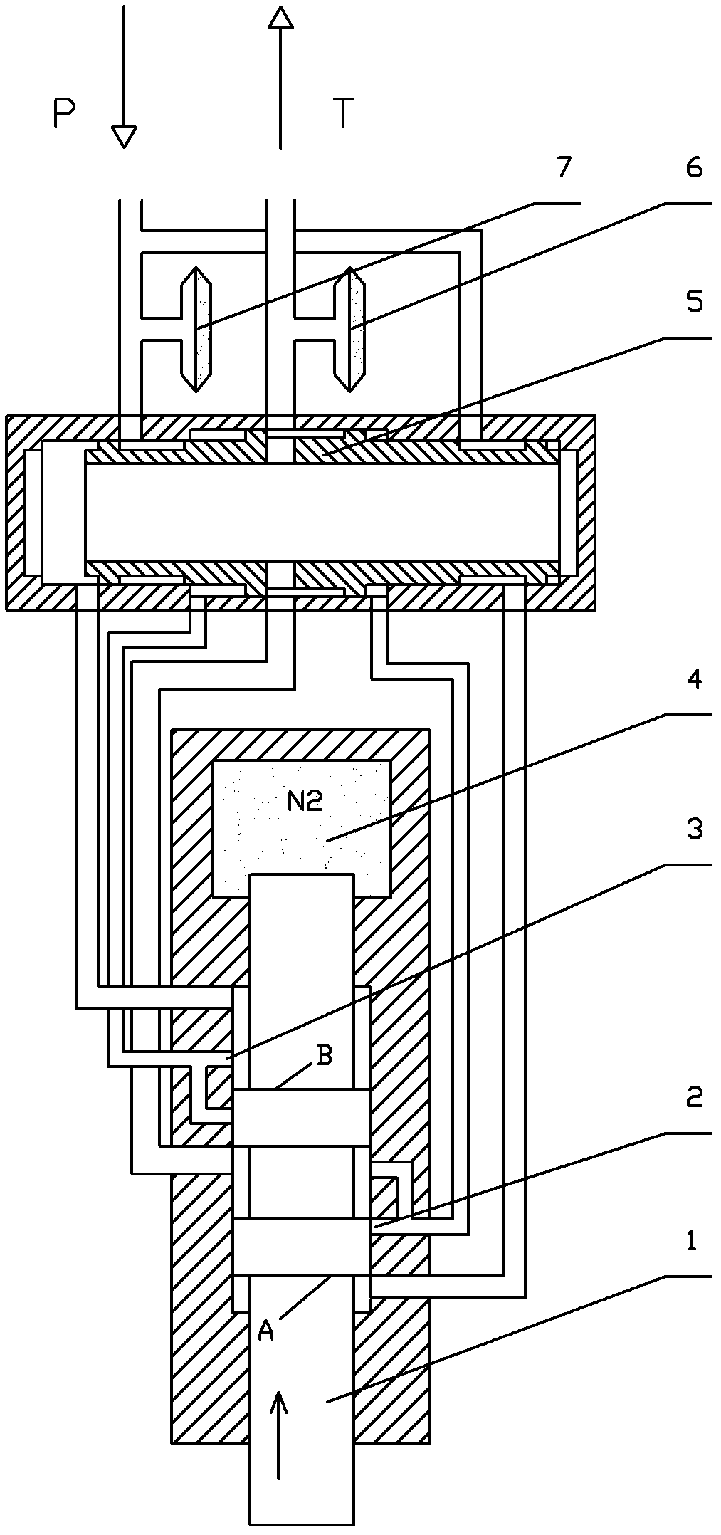
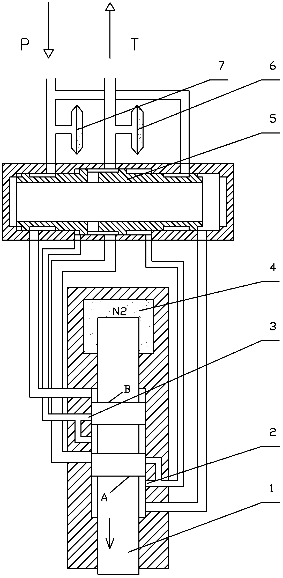
[0016] A gas-hydraulic combined hydraulic impactor, including a double-sided oil inlet and discharge impactor, the double-sided oil inlet and discharge impactor includes a piston 1, a hydraulic control reversing valve and an oil circuit, and the double-sided oil inlet and discharge impactor The tail end of the piston 1 is provided with a nitrogen chamber 4, the connection between the nitrogen chamber 4 and the piston 1 is sealed and the tail end of the piston 1 is arranged in the nitrogen chamber 4 during the return stroke and stroke. Inside, the hydraulic control reversing valve includes a valve body 8 and a valve core 9, the valve core 9 is installed in the valve body 8, and the valve body 8 includes two high-pressure oil inlets (10, 11), one Piston-cylinder front chamber connection port 12, a piston-cylinder rear ch...


PUM


Abstract

The invention discloses a gas-liquid combined hydraulic impacter. The gas-liquid combined hydraulic impacter disclosed by the invention comprises a valve body, a valve core and a double-sided oil feed / discharge impacter, wherein the double-sided oil feed / discharge impacter comprises a piston, a pilot operated directional control valve and an oil way; the tail end of the piston is provided with a nitrogen chamber, a joint of the nitrogen chamber and the piston is hermetically connected, and the tail end of the piston is arranged in the nitrogen chamber both in the processes of returning and stroking. The impacter disclosed by the invention is high in energy utilization ratio, so that the oil supply quantity of a valve pushing cavity is sufficient, thereby preventing the occurrence of a 'suction' phenomenon and reducing hydraulic shocks, vibration and noises, in such a way, the operations of the pilot operated directional control valve and the piston are stable, and the service lives of the pilot operated directional control valve and the piston are prolonged.

Description

technical field [0001] The invention relates to the technical field of engineering machinery, in particular to a gas-hydraulic combined hydraulic impactor. Background technique [0002] Hydraulic impact device - or hydraulic impact breaker, has been widely used in all walks of life in society, in the transportation and construction industries, for the demolition of concrete buildings and cement pavement, in the metallurgical industry, for the removal of smelting slag 1. Disintegration and cleaning of mixed iron cars in steel mills. In mining engineering, it is used in the stope and the ore grid screen for secondary crushing of large ore rocks. At present, an important emerging technology industry has formed in the world. At present, there are mainly three types of structural forms of hydraulic impact devices: (1) hydrostatic principle structure; (2) nitrogen expansion principle structure; (3) hydraulic-nitrogen combined action principle structure. [0003] The existing imp...

Claims


Application Information

Patent Timeline
Patent Type & Authority Applications(China)
IPC IPC(8): F15B15/00B25D9/00B25D9/06
Inventor 张新
Owner CHANGSHA UNIVERSITY OF SCIENCE AND TECHNOLOGY
Why Eureka
Try Eureka