Micro attitude and heading reference system based on 3D stereoscopic packaging technology

A three-dimensional, reference system technology, applied in the field of inertial sensing systems, can solve the problems of large installation errors, high precision, and high processing costs, and achieve the effects of improving structural reliability, reducing non-orthogonal errors, and reducing installation errors

Active Publication Date: 2012-01-11
威海中宏微宇科技有限公司
View PDF12 Cites 25 Cited by
  • Summary
  • Abstract
  • Description
  • Claims
  • Application Information

AI Technical Summary

Problems solved by technology

[0008] 1. The metal frame is too heavy, which greatly increases the weight of the miniature attitude and heading reference system, which is not conducive to its development towards light weight
[0009] 2. The size of the micro-attitude and heading reference system is too large, which is not conducive to breaking through the limitation of the internal space of the carrier, and is not conducive to its development towards miniaturization
[0011] 4. There are many installation procedures, the introduction of installation errors is large, and the processing cost is high
[0012] 5. The micro-attitude and heading reference system does not include a microprocessor and does not have independent computing functions
[0013] 6. Using single-sided mounting technology, the available space is limited, which is not conducive to the expansion of devices
[0014] 7. The combination of multiple printed circuit boards is not suitable for high-density electrical connections
[0015] Therefore, the micro-attitude and heading reference system under the current technology cannot take into account the requirements of small size, light weight, high precision, low cost and strong scalability.

Method used


Image

  • Micro attitude and heading reference system based on 3D stereoscopic packaging technology
  • Micro attitude and heading reference system based on 3D stereoscopic packaging technology
  • Micro attitude and heading reference system based on 3D stereoscopic packaging technology

Examples


Embodiment Construction

[0038] The present invention will be further described in detail below in conjunction with the accompanying drawings and embodiments.

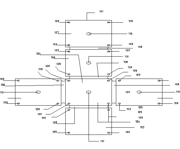
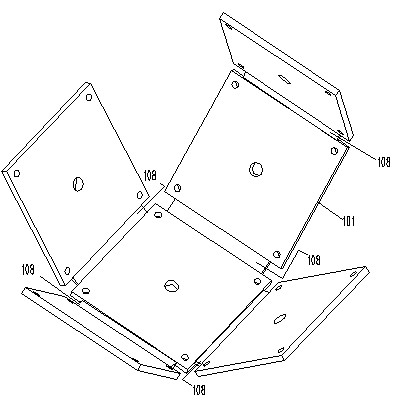
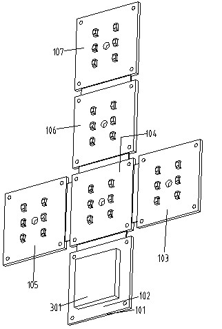
[0039] like Figure 1 to Figure 8 As shown, the reference numbers are as follows: multilayer rigid-flexible board 101, first rigid printed circuit board part 102, second rigid printed circuit board part 103, third rigid printed circuit board part 104, fourth rigid printed circuit board part 105, fifth rigid printed circuit board part 106, sixth rigid printed circuit board part 107, ligament 108, positioning hole 109, circuit board mounting hole 110, passive element 201, microprocessor 301, three-dimensional space integrated base 401, left Plane 402, Front Plane 403, Lower Plane 404, Rear Plane 405, Right Plane 406, Upper Plane 407, Positioning Screw 409, Base Mounting Hole 410, Glue Pouring Groove 411, Main Device Groove 412, Zigzag-shaped Secondary Device Mounting Groove 413 , a single-axis gyroscope 701 , a three-axis accelerometer 702 , an...


PUM


Abstract

The invention discloses a micro attitude and heading reference system based on 3D stereoscopic packaging technology. The system provided by the invention comprises a 3D integrated pedestal which is positioned in a core and is shaped as a hexahedron; the external surface of the 3D integrated pedestal is tightly covered with multilayer rigid-flexible PCB; one side of the multilayer rigid-flexible PCB is equipped with a microprocessor, and other five sides are respectively provided with three single-shaft gyroscopes, a triaxial accelerometer and a triaxial magnetic sensor; one side of the 3D integrated pedestal is equipped with a main device slot, and the microprocessor is embedded inside the main device slot; set screws are mounted at four corners of each surface of the 3D integrated pedestal and are also fixedly connected with corresponding positions of the multilayer rigid-flexible PCB; the 3D integrated pedestal is moulded at one step, and each shaft of the sensor is respectively parallel to each other and mutually orthogonal; various sensors are installed by the adoption of multilayer printed circuit boards so as to minimize the volume of the whole pedestal; the microprocessor is introduced to reach independent operational and data processing functions.

Description

technical field [0001] The invention relates to the technical field of inertial sensing systems in electronic navigation and control, in particular to a miniature attitude and heading reference system based on three-dimensional packaging technology. Background technique [0002] Attitude and Heading Reference System, abbreviated as AHRS in English, is mainly composed of a three-axis gyroscope, a three-axis accelerometer, a three-axis geomagnetic sensor and a microprocessor. According to the requirements of the principle of inertial navigation, the three sensitive axes X of the accelerometer A , Y A ,Z A , the three sensitive axes X of the gyroscope G , Y G ,Z G , the three sensitive axes of the geomagnetic sensor X M , Y M ,Z M ; Each axis of X, Y, and Z on the front side must be parallel, and each axis of X, Y, and Z that cross each other must also be orthogonal to each other. Under this premise, the microprocessor calculates all the sensing data, and the system ca...

Claims


Application Information

Patent Timeline
Patent Type & Authority Applications(China)
IPC IPC(8): G01C21/16G01C21/20
Inventor 王皓冰朱巍雷家波
Owner 威海中宏微宇科技有限公司
Why Eureka
Try Eureka