
Microwave digestion furnace chamber

A technology of microwave digestion and furnace cavity, which is applied in the field of analytical chemical instruments, can solve problems such as hidden safety hazards and difficult operation, and achieve the effects of preventing microwave leakage, improving work efficiency, and ensuring personal safety

Active Publication Date: 2012-01-11
上海新拓分析仪器科技有限公司
View PDF9 Cites 10 Cited by
  • Summary
  • Abstract
  • Description
  • Claims
  • Application Information

AI Technical Summary

Problems solved by technology

[0012] The main purpose of the present invention is to provide a microwave digestion chamber to solve the technical problems mentioned in the background technology that it will bring safety hazards to the staff and difficult to operate.

Method used


Image

  • Microwave digestion furnace chamber
  • Microwave digestion furnace chamber
  • Microwave digestion furnace chamber

Examples


Embodiment Construction

[0032] This specific embodiment will be further described in conjunction with the accompanying drawings.

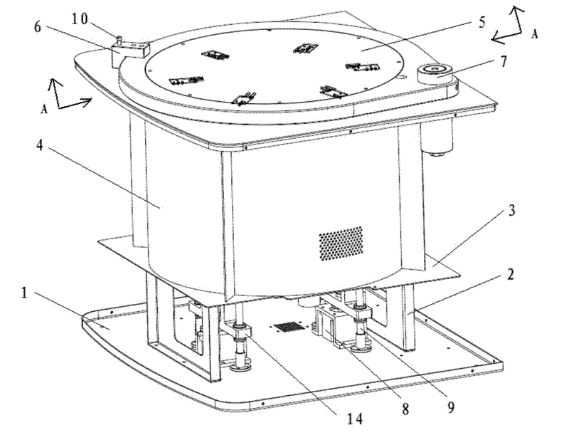
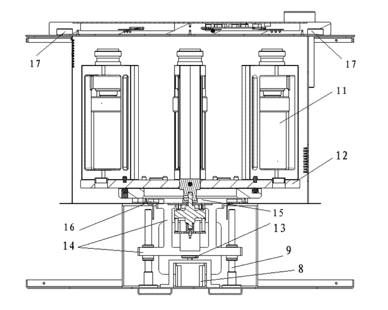
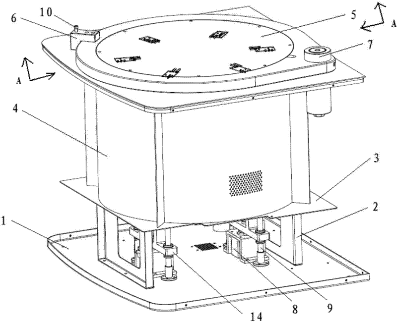
[0033] refer to figure 1 and figure 2 It can be seen that a microwave digestion cavity includes a base 1, a bracket 2, a bottom plate 3, a cavity 4, a movable cover 5, a buckle 6, a rotating shaft 7, a motor 8, a sliding rod 9, a shaft 10, a digestion tank 11, and a turntable 12. Strut 13, lifting part 14, movable bottom plate 15, anti-flow groove 16 and anti-flow groove 17.

[0034] The bracket 2 is fixedly connected between the base 1 and the base plate 3 , the base plate 3 is fixedly connected with a cavity 4 , the cavity 4 is provided with a movable cover 5 , and the movable cover 5 is movably connected with the cavity 4 through a rotating shaft 7 . Since the movable cover 5 is arranged on the top of the microwave digestion chamber cavity 4, if the pressure relief of the microwave digestion chamber is insufficient or not timely during use, the movable cover 5 will ...


PUM


Abstract

Provided is a microwave digestion furnace chamber which comprises a pedestal, a cavity, a base plate which is fixed at the bottom of the cavity, a support which is fixed between the base plate and the pedestal, and a digestion pot. The microwave digestion furnace chamber is characterized by further comprising a rotary disc which is arranged at the bottom in a tank body of the cavity, wherein, thedigestion pot is arranged on the rotary disc, an elevating assembly which is arranged on the pedestal and comprises a movable base plate that is arranged between the rotary disc and the elevating assembly, located at a same horizontal plane where the base plate is located and provided with an anti-current groove, and a movable cover which is arranged at the upper end of the cavity, movably connected with the cavity through a rotating shaft and provided with an anti-current groove. The beneficial effects of the invention are as follows: microwave leakage can be prevented; personnel safety of surrounding workers can be ensured; manpower is saved; working efficiency is improved.

Description

technical field [0001] The invention relates to the field of analytical chemical instruments, in particular to a microwave digestion furnace cavity. Background technique [0002] In modern analytical chemistry, the analysis process of inorganic elements mainly includes two parts: sample pretreatment and instrument detection. In the whole analysis process, the key to determining the speed and quality of sample analysis is the sample pretreatment technology and method. However, the classic sample processing methods such as acid hydrolysis, alkali fusion, and dry ashing commonly used in existing laboratories not only have shortcomings such as long time consumption, high energy consumption, large amount of reagents, cross-contamination of samples, and volatilization loss of target elements. , and the acid mist produced will pollute the environment and endanger the operator. For this reason, people have been trying to find something that can overcome the shortcomings of these cl...

Claims


Application Information

Patent Timeline
IPC IPC(8): G01N1/44
Inventor 余伟杰张和清
Owner 上海新拓分析仪器科技有限公司
Learn More