Method for separating and identifying kinematical parameters of mechanical arm

An order-of-magnitude, error-prone technology applied in the field of robot calibration to overcome limitations

Inactive Publication Date: 2012-01-11
BEIJING UNIV OF POSTS & TELECOMM
View PDF4 Cites 19 Cited by
  • Summary
  • Abstract
  • Description
  • Claims
  • Application Information

AI Technical Summary

Problems solved by technology

[0004] The purpose of the present invention is to provide a parameter separation and identification method for the shortcomings of the current kinematics calibration method, which is simple to operate and greatly improves the accuracy

Method used


Image

  • Method for separating and identifying kinematical parameters of mechanical arm
  • Method for separating and identifying kinematical parameters of mechanical arm
  • Method for separating and identifying kinematical parameters of mechanical arm

Examples


Embodiment Construction

[0014] (1) Modified D-H model

[0015] In the classic D-H model, there are singular points when two adjacent axes are parallel or close to parallel. On this basis, a transformation of rotating β angle around the y-axis is added to overcome the problem of singular points. The corrected coordinate transformation matrix is:

[0016] T i - 1 = Rot ( x , α i - 1 ) Trans ( x , a i - 1 ) Rot ( z , θ i ) Trans ( z ...


PUM


Abstract

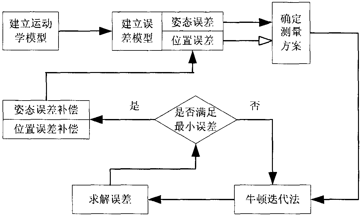
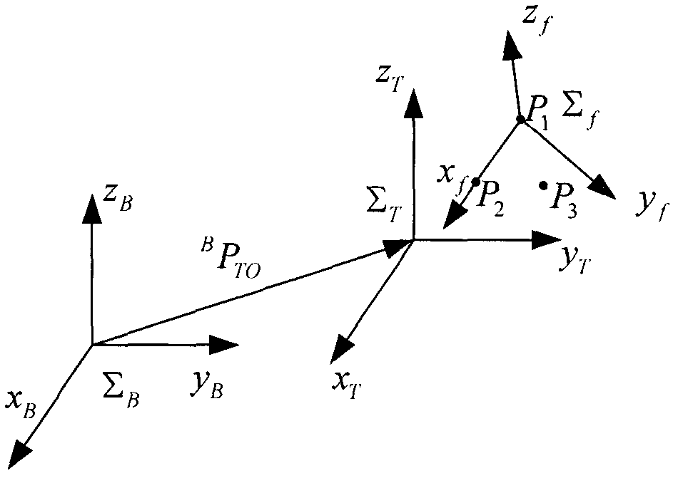
The invention relates to a method for separating and identifying kinematical parameters of a mechanical arm. On the basis of a laser tracking instrument position measurement principle and a mechanical arm differential kinematics principle, a D-H (Denavit-Hartenberg) parameter identifying method of the mechanical arm without counting joint position errors is provided by separating a posture matrix from a position vector in a homogeneous transformation matrix of an end effector. The method for separating and identifying the kinematical parameters of the mechanical arm comprises the following steps of: firstly identifying a posture parameter by measuring the posture matrix of the end effector in a basic system; secondly, identifying the separated position parameters by utilizing the identified posture parameter and the practically-measured end position; and finally realizing the identification of the kinematical parameters of the mechanical arm.

Description

technical field [0001] The invention relates to the field of robot calibration, in particular to a method for identifying kinematics parameters of a manipulator that separates and identifies attitude parameters and position parameters. Background technique [0002] Robot parameter identification is an important means to improve the accuracy, which is of great significance to the success of robot off-line programming and vision-guided operation. The geometric parameter error of the connecting rods of the robot is the most important part of the positioning error of the robot. It is mainly caused by the deviation between the actual geometric parameters and the nominal parameter values ​​of the connecting rods during the manufacturing and installation process. It is generally regarded as a system error. In addition, some influencing factors such as environment, mechanical deformation are considered as random errors. The so-called identification is the process of using advanced...

Claims


Application Information

Patent Timeline
Patent Type & Authority Applications(China)
IPC IPC(8): G06T7/20G01B11/00
Inventor 贾庆轩朱宁宁陈钢孙汉旭张岩
Owner BEIJING UNIV OF POSTS & TELECOMM
Why Eureka
Try Eureka