Ventilating and radiating system for switch cabinet chamber of semi-buried box-type substation

A box-type substation, ventilation and heat dissipation technology, applied in the cooling/ventilation of substation/switchgear, etc., can solve the problems of increasing uncertain factors, insufficient guarantee of transformer room sealing, difficulty in ensuring safe operation of transformers, etc., to achieve Avoid water ingress, excellent effect, and ensure sealing effect

Active Publication Date: 2012-01-11
浙江安可电气科技有限公司
View PDF4 Cites 11 Cited by
  • Summary
  • Abstract
  • Description
  • Claims
  • Application Information

AI Technical Summary

Problems solved by technology

One side of the inlet / outlet hole is the transformer room, and the other side is the cable trench. Once the sealing of the transformer room is not fully guaranteed, the water in the cable trench will seep into the lower box, affecting the safe operation of the transformer.
Moreover, the more outlet holes, the more difficult it is to maintain the tightness of the transformer room, increasing uncertainties and making it difficult to ensure the safe operation of the transformer

Method used


Image

  • Ventilating and radiating system for switch cabinet chamber of semi-buried box-type substation
  • Ventilating and radiating system for switch cabinet chamber of semi-buried box-type substation
  • Ventilating and radiating system for switch cabinet chamber of semi-buried box-type substation

Examples


Embodiment Construction

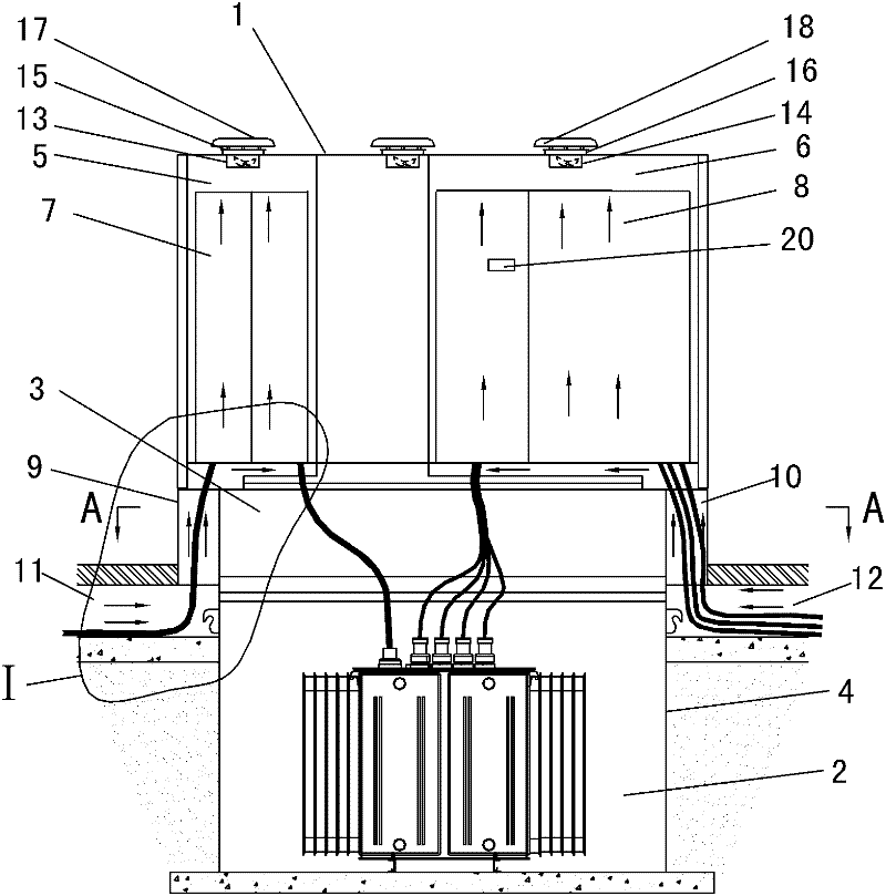
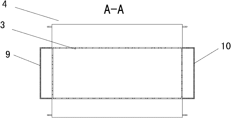
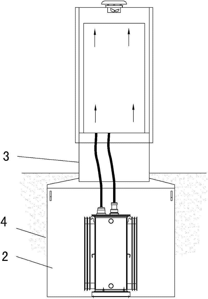
[0022] Such as figure 1 As shown: the semi-buried box-type substation involved in the present invention includes an upper box body 1 and a lower box body 2, most of the lower box body 2 is buried underground, part of its neck 3 is exposed to the ground surface, and the lower part 4 is completely buried below the ground surface . A high-voltage cabinet room 5 and a low-voltage cabinet room 6 are respectively arranged on the left and right sides of the upper box, in which a high-voltage cabinet 7 and a low-voltage cabinet 8 are respectively placed. The surroundings of the high-voltage cabinet room 5 and the low-voltage cabinet room 6 are sealed, and the bottom and top of the high-voltage cabinet 7 and the low-voltage cabinet 8 are connected. The two sides of the neck 3 of the upper box body are respectively installed with the high-voltage cabinet room air inlet duct 9 and the low-voltage cabinet room air inlet duct 10 as the cable inlet and outlet channels, and the lower openin...


PUM


Abstract

The invention provides a ventilating and radiating system for a switch cabinet chamber of a semi-buried box-type substation, which comprises a lower box body as a transformer chamber and an upper box body as the switch cabinet chamber, wherein of the big part of the lower box body is buried under the ground; and a certain height of neck is exposed out of the ground. The ventilating and radiating system is characterized in that a high-voltage cabinet chamber is arranged at one side in the upper box body; a low-voltage cabinet chamber is arranged at the other side in the upper box body; a high-voltage cabinet chamber air inlet channel and a low-voltage cabinet chamber air inlet channel which are respectively used for allowing cables to pass in and out and ventilating are arranged on two sides at the neck of the lower box body; a high-voltage cable trench and a low-voltage cable trench are respectively introduced into the lower part of the air inlet channel; and exhaust outlets are respectively arranged at the upper part of the high-voltage cabinet chamber and the upper part of the low-voltage cabinet chamber. No wire through hole is arranged on the lower box body, thus the sealing property of the lower box body is ensured; the cable trenches are used as cold air sources so as to ensure that all air entering the upper box body is cold air; and an air inlet and an air outlet are respectively arranged at the bottom and the upper part or the top part of the lower box body, thus local circulation can be avoided and the integral ventilation and radiation of the high-voltage cabinet, and the low-voltage cabinet can be realized.

Description

technical field [0001] The invention belongs to the technical field of semi-buried box-type substations, in particular to a ventilation and cooling system for a switch cabinet room of a semi-buried box-type substation. Background technique [0002] In existing semi-buried box-type substations, natural exhaust and forced exhaust are usually used for ventilation and heat dissipation of the upper box of the switch cabinet room. Two upper and lower louver ventilation holes are respectively set on the two side facades of the upper box body (for example: the utility model patent with the notification number CN201656306), which is used as a natural heat dissipation channel; Install exhaust fan to realize forced exhaust. These two exhaust methods, due to the close distance between the air inlet and the air outlet, will form local convection, and it is difficult to achieve ventilation and heat dissipation of the entire cabinet room; especially in summer, the ambient temperature itse...

Claims


Application Information

Patent Timeline
Patent Type & Authority Applications(China)
IPC IPC(8): H02B1/56
Inventor 陶勤杨永林潘吉潘健叶阿明孙榆
Owner 浙江安可电气科技有限公司
Why Eureka
Try Eureka