Equipment for renewing air in a plurality of rooms by means of a dual flow heat exchanger provided in each room

A technology for exchangers and rooms, used in lighting and heating equipment, shielding with air flow, energy recovery systems for ventilation and heating, etc., can solve the problems of inability to adjust air parameters, pollution, increase costs, etc., and achieve length reduction. , The effect of reducing energy consumption and reducing pressure loss

Inactive Publication Date: 2012-01-11
皮埃尔.维罗尼尔 +5
View PDF4 Cites 1 Cited by
  • Summary
  • Abstract
  • Description
  • Claims
  • Application Information

AI Technical Summary

Problems solved by technology

However, the disadvantage of this device is that it is not possible to independently adjust the air parameters for each room, especially the temperature
Furthermore, the shared air intake ducts have outlets for contamination, especially of the bacterial type in the rooms served by these ducts
Another disadvantage is that the air inlet ducts (common and separate) to the rooms must be installed particularly well to be able to guarantee the parameters of the incoming air, which are defined by the common heat exchanger 160 remote from the room for re-airing; this This mounting configuration substantially increases the cost of these tubes
Furthermore, in such installations there is a risk of mixing exhaust and intake air at the level of the generator

Method used


Image

  • Equipment for renewing air in a plurality of rooms by means of a dual flow heat exchanger provided in each room
  • Equipment for renewing air in a plurality of rooms by means of a dual flow heat exchanger provided in each room
  • Equipment for renewing air in a plurality of rooms by means of a dual flow heat exchanger provided in each room

Examples


Embodiment Construction

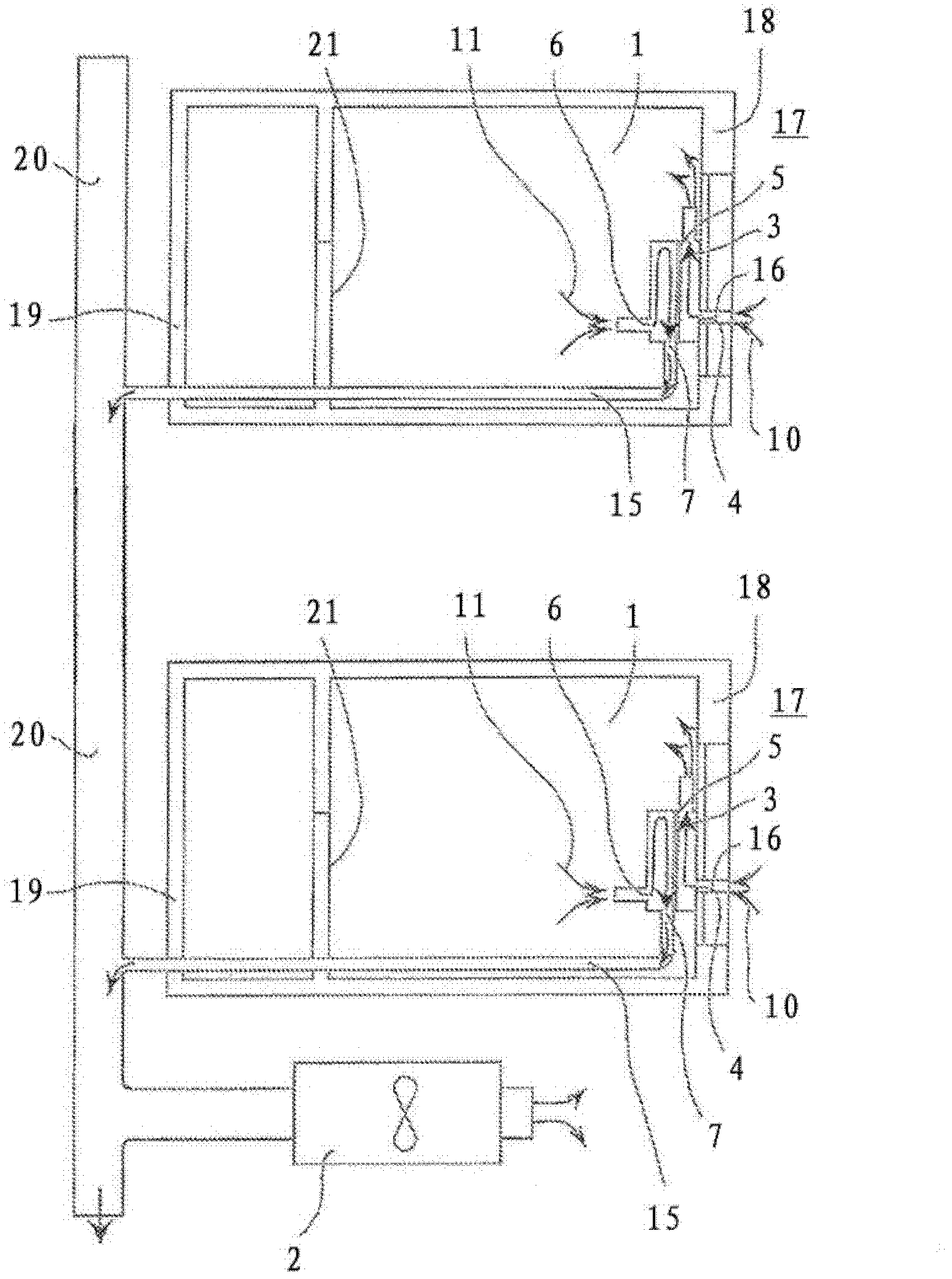
[0043] The equipment used to refresh the air in multiple rooms 1 (more precisely in the two rooms in this example) is shown in image 3 or 5, and partially displayed in Figure 4 , the equipment includes:

[0044] Single flow airflow generator 2, located outside the two rooms 1,

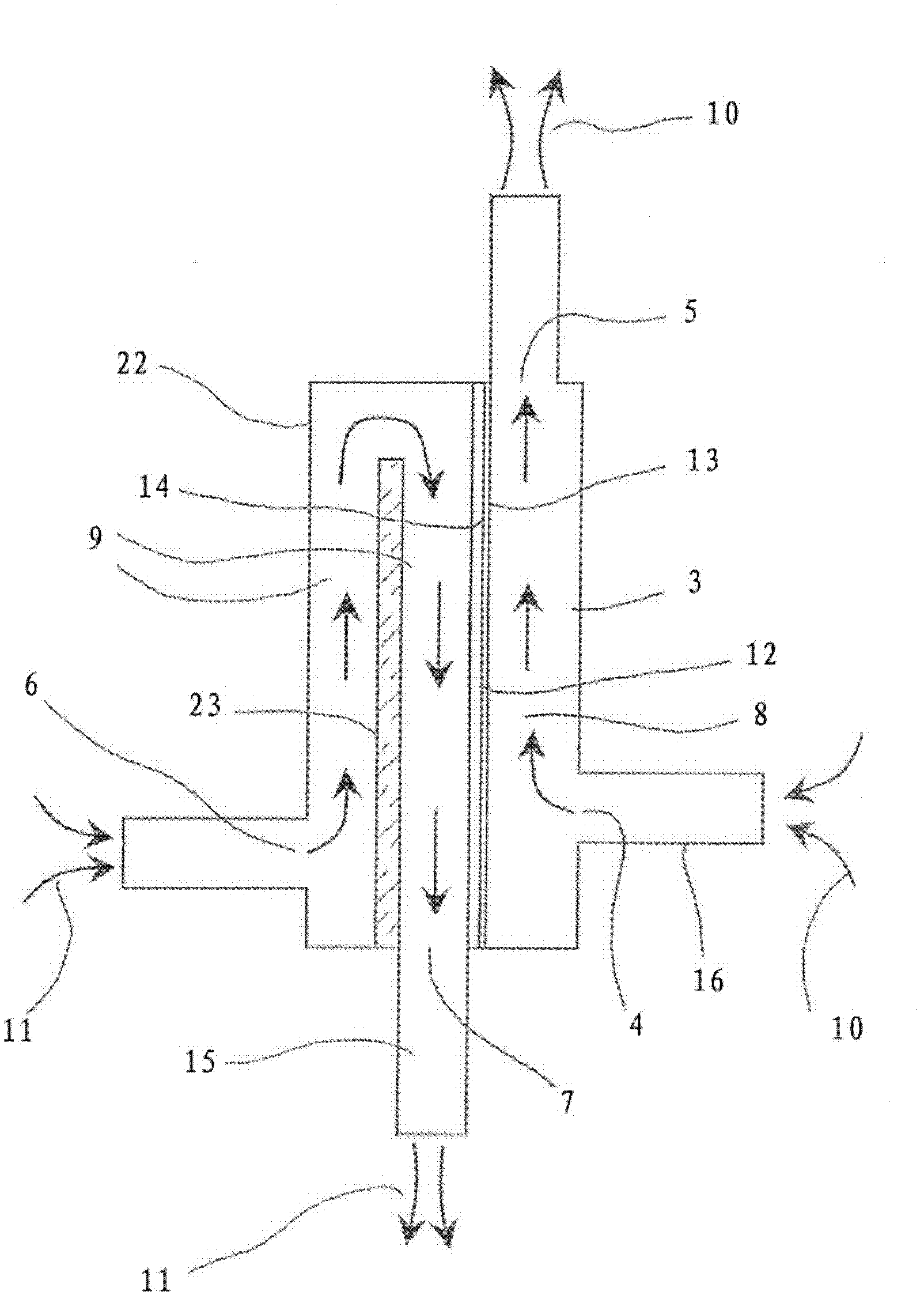
[0045] A double-flow heat exchanger 3, for example in each room 1, the double-flow heat exchanger 3 in each room 1 comprising:

[0046] Inlet 4 for incoming air flow 10 into room 1,

[0047] outlet 5 for the incoming airflow into room 1,

[0048] Inlet 6 for exhaust air flow 11 from room 1,

[0049] Outlet 7 for exhaust air flow 11 from room 1,

[0050] flow inlet inner tube 8, connecting the inlet 4 and the outlet 5, for letting the air flow 10 into the room 1,

[0051] Flow outlet inner tube 9, connecting inlet 6 and outlet 7, for letting air flow 11 out of room 1,

[0052] a heat exchange wall 12, one surface 13 of which forms part of the flow inlet inner tube 8 and whose second surface 14 ...


PUM


Abstract

The invention relates to equipment for renewing the air of a plurality of rooms (1), comprising: a common single-flow airflow generator (2) arranged inside the rooms for extracting air from the rooms; a dual flow heat exchanger (3) arranged inside each room (1), comprising: an inlet opening (4) for the airflow (10) entering the room; an outlet opening (5) for the airflow (10) entering the room; an inlet opening (6) for the airflow (11) exiting the room; an outlet opening (7) for the airflow (11) exiting the room; a flow inlet inner duct (8) connecting the inlet (4) and outlet (5) openings for the airflow entering the room; a flow outlet inner duct (9) connecting the inlet (6) and outlet (7) openings for the airflow exiting the room; an exchange wall (12) having a first surface (13) defining a portion of said flow inlet inner duct (8) and a second surface (14) opposite the first defining a portion of the flow outlet inner duct (9); a plurality of individual ducts (15) for extracting air from the rooms, an individual extraction duct for a room connecting the flow generator to the outlet (7) of the heat exchanger (3) of the room for the airflow (11) exiting the room via a common air extraction collecting duct (20); an air inlet duct (16) in each room, individually allocated to each room, in which flows only the airflow (10) entering said room, and connecting the inlet opening (4) of the dual flow heat exchanger (3) of each room, for the airflow (10) entering the room (1), to the external environment (17).

Description

technical field [0001] The invention relates to a device for renewing the air in a plurality of rooms, comprising a single-flow airflow generator located outside the plurality of rooms for the common exhaustion of polluted air from the plurality of rooms. Background technique [0002] The prior art includes several such devices. [0003] For example figure 1 Schematically shown, a single-flow controlled mechanical ventilation device (referred to as a single-flow CMV) includes a single-flow airflow generator 102, typically consisting of a fan installed outside the room 101, such as in an attic space of a dwelling, where the fan The air in the room is renewed via an inlet 152 and an outlet 153 for letting air in and out of the room 101, which are provided at two substantially opposite locations in the room, for example under a door 150 for letting air in and out. Exhaust from the room 101 and on the frame of a window type opening are used to let air enter the room 101 from t...

Claims


Application Information

Patent Timeline
Patent Type & Authority Applications(China)
IPC IPC(8): F24F7/08F24F12/00
CPCF24F2012/007Y02B30/563Y02B30/16F24F7/08F24F12/006Y02B30/56
Inventor 皮埃尔.维罗尼尔伯纳德.西奥斯皮埃尔.阿佩塞特克弗雷德里克.卡拉马诺斯帕斯卡尔.卡泽里斯阿兰.阿弗里尔
Owner 皮埃尔.维罗尼尔
Why Eureka
Try Eureka