Edge termination with improved breakdown voltage

An endpoint, edge technology, applied in the field of edge endpoint area structure, can solve problems such as breakdown and collapse

Active Publication Date: 2012-01-11
MAXPOWER SEMICON INC
View PDF4 Cites 16 Cited by
  • Summary
  • Abstract
  • Description
  • Claims
  • Application Information

AI Technical Summary

Problems solved by technology

There are a number of disadvantages to layouts using such shallow body junction devices, such as metal-oxide-semiconductor field-effect transistors with recessed field plate (RFP) structures
For example, since the bottom of the

Method used


Image

  • Edge termination with improved breakdown voltage
  • Edge termination with improved breakdown voltage
  • Edge termination with improved breakdown voltage

Examples


Embodiment Construction

[0112] Here, many innovative technologies of the application will be described with particular reference to the preferred specific embodiments of the application (by way of example, but not limited thereto). This application describes a number of specific examples, however, the following specific examples should not be taken as limitations of the claims.

[0113] For simplicity and clarity of view, the drawings illustrate the general manner of construction, and descriptions and details of known features and techniques are omitted to avoid unnecessarily obscuring the present invention. In addition, components in the drawings are not drawn according to actual scale, and some areas or components may be drawn enlarged to help understand the embodiments of the present invention.

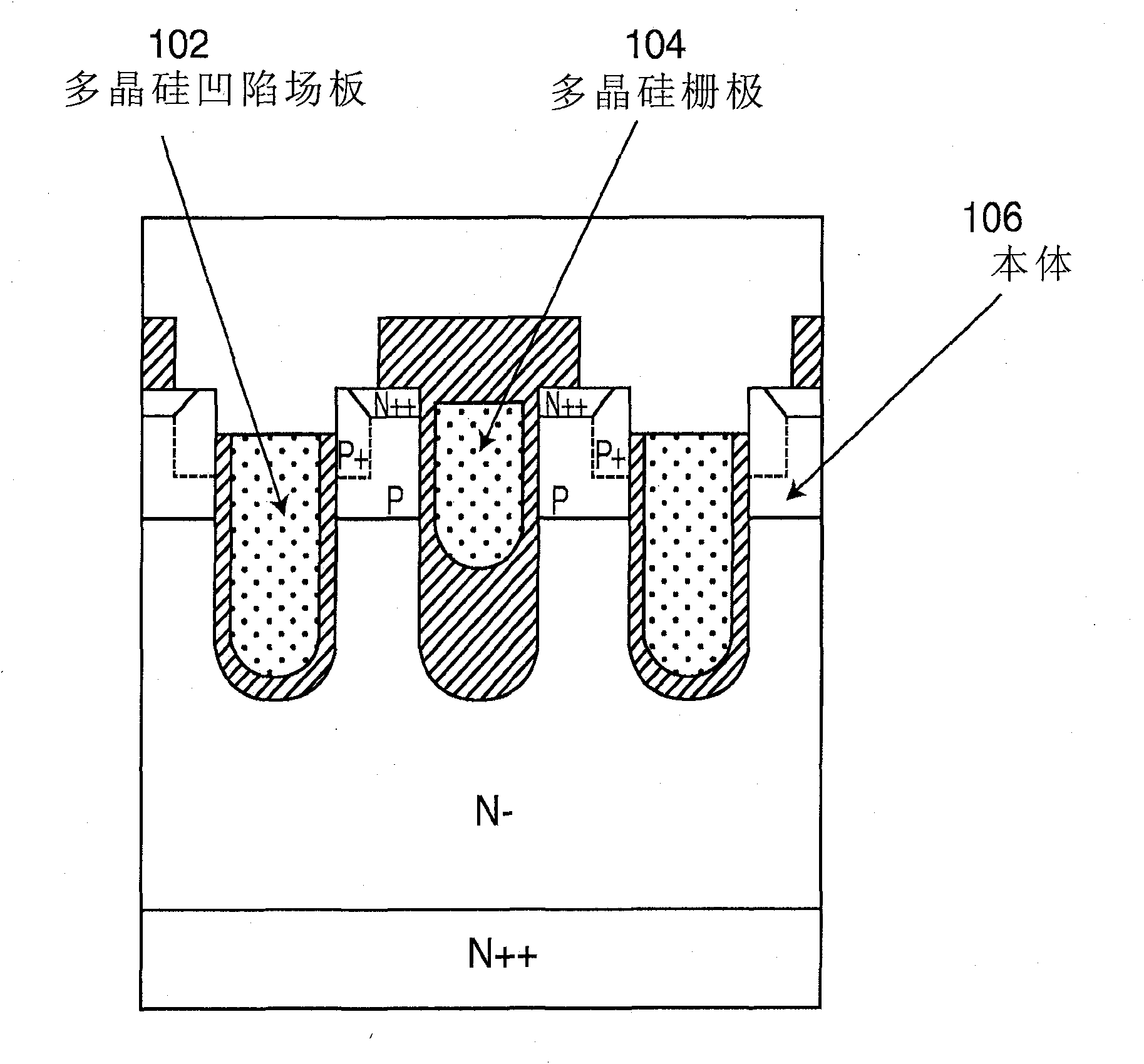
[0114] It should be considered and noticed that this design is applied to both n-type and p-type metal oxide semiconductor field effect transistors; for the sake of clarity, the structure of n-type metal ...


PUM


Abstract

A MOSFET switch which has a low surface electric field at an edge termination area, and also has increased breakdown voltage. The MOSFET switch has a new edge termination structure employing an N-P-N sandwich structure. The MOSFET switch also has a polysilicon field plate configuration operative to enhance any spreading of any depletion layer located at an edge of a main PN junction of the N-P-N sandwich structure.

Description

[0001] Cross-references to related applications: [0002] This application claims priority to U.S. Applications Serial No. 61 / 125,892, filed April 29, 2008, and U.S. Application Serial No. 61 / 065,759, filed February 14, 2008, the entire contents of which are hereby incorporated by reference . technical field [0003] The present invention relates to power transistors or switches, and more particularly to edge terminal region structures of power MOSFETs with shallow body junctions. Background technique [0004] To improve the performance of power semiconductor MOSFET switches, short channels can be used to reduce conduction and switching power losses. An example of such an advanced power Mosfet switch is a Recessed Field Plate (RFP) design to limit the extension of the depletion region into the body region. Such a structure will form a shorter channel length without suffering breakdown and high leakage current. US Patent Application No. 2008 / 0073707 A1 filed by Derwig has ...

Claims


Application Information

Patent Timeline
IPC IPC(8): H01L21/336H01L29/78
CPCH01L29/1095H01L29/0696H01L29/41741H01L29/7811H01L29/0634H01L29/402H01L29/404H01L29/4238H01L29/0615H01L29/0619H01L29/0623H01L29/0661H01L29/407H01L2224/02166
Inventor 曾军穆罕默德·恩·达维希苏世宗
Owner MAXPOWER SEMICON INC
Why Eureka
Try Eureka